1: GSN Introduction
26
Geodesic Sensor Net Technical Manual
S-MAN-200-GSNR-001 • January 31, 2007
Basic Operation
Physically, the GSN connects to the amplifier either directly (in the GES 120 or 140) or
via a Geodesic Sensor Net interface cable (GSNIC; in the GES 200, 250, or 300). (For
more information about the GSNIC, see the
GES Hardware Technical Manual
.)
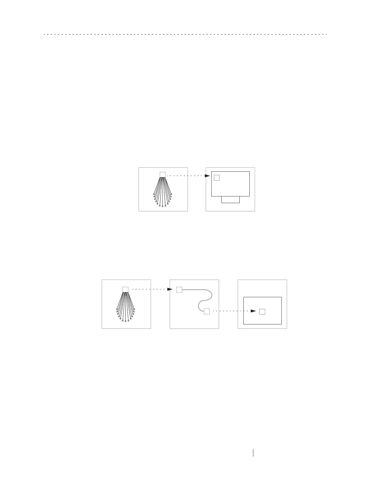
In the GES 120 or 140, the leads of a 32-channel GSN are bundled and terminate in a
connector that plugs into the Hypertronics connector on the front of the Neurotravel
amplifier. This is shown in Figure 1-5.
In the GES 200, 250, or 300, the leads of a 64-, 128-, or 256-channel GSN are bundled
and terminate in a connector that plugs into one end of the GSNIC. The GSNIC’s
other end plugs into the Net Amps 200 or 300 amplifier. This is shown in Figure 1-6.
The GSNIC allows the subject to be positioned conveniently within a meter or two of
the amplifier. The GES 200, 250, or 300 ships with a GSNIC that can handle the
appropriate sensor density of the users’ Nets.
Figure 1-5. Sensor array and Neurotravel amplifier
Figure 1-6. GSN, GSNIC, and Net Amps amplifier