9: Replacing GSN Parts
95
Geodesic Sensor Net Technical Manual
S-MAN-200-GSNR-001 • January 31, 2007
5
Trim the sponge of the new electrode so that it protrudes 0.5 cm. from the
sensor housing.
6
To avoid tangling, it is important to thread the replacement electrode’s wire
along the same path as the electrode with either the previous number or the
following number. Be sure to thread the wire through the correct hole in the
sliding wire guide.
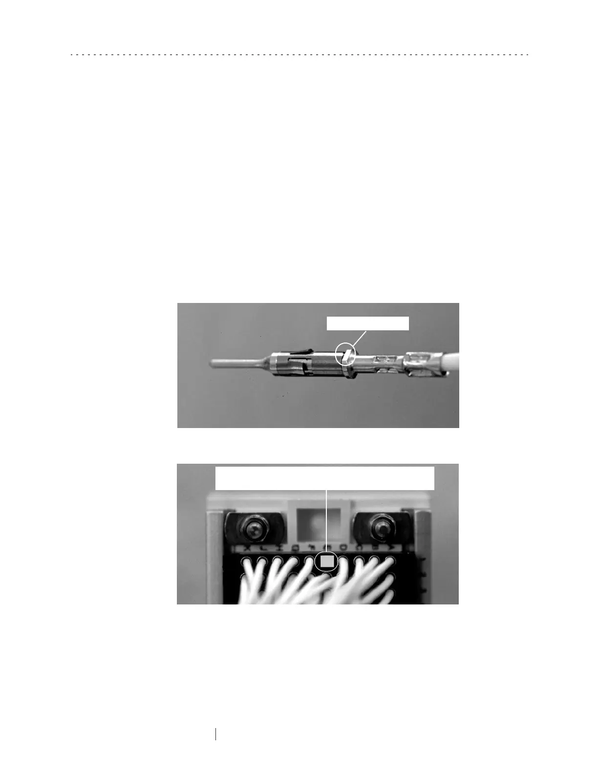
7
Insert the contact into the appropriate location in the connector, making sure
that the flat sides of the contact are lined up parallel to the long sides of the
connector opening (Figure 9-12 and Figure 9-13). Push the contact into place
until you hear a click.
Note: A condensed version of the replacement instructions are included on the back of the
replacement electrode package label (Figure 9-1).
Figure 9-12. Enlarged view of Hypertronics contact
Figure 9-13. View of connector before inserting contact
Flat side of the contact
When inserting the contact, align its flat sides parallel to the long
sides of the rectangular opening where it is to be inserted.