C: GSN Pinouts
133
Geodesic Sensor Net Technical Manual
S-MAN-200-GSNR-001 • January 31, 2007
Pinout Tables
Listed in Table C-1 are the pinout schemes contained in this appendix.
Table C-1. Pinout tables
Table Pinout Comment
Table C-2 Sensor to 32-, 64-, and 128-pin plug Sensor number to Hypertronics pin number
Table C-3 Sensor to 256-pin plug Sensor number to Hypertronics pin number
Table C-2. Sensor to 32-, 64-, and 128-pin plug
Sensors
1–10 Pin
Sensors
11–20 Pin
Sensors
21–30 Pin
Sensors
31–40 Pin
1 1A112A213A314A
2 1B122B223B324B
3 1C132C233C334C
4 1D142D243D344D
5 1E152E253E354E
6 1F162F263F364F
7 1G172G273G374G
8 1H182H283H384H
9 1I192J293J394J
10 1J 20 2K 30 3K 40 4K
Note: In the following table, sensors 65–128 and their corresponding pin numbers
apply
only
to the 128-channel Net. These sensors/pins are absent in the case of the
64-channel Net. For the 32-channel Net, sensors 33–128 and their corresponding pin
numbers are absent.
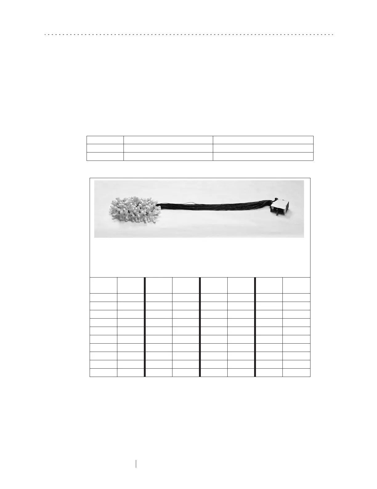
128-channel GSN