9: Replacing GSN Parts
92
Geodesic Sensor Net Technical Manual
S-MAN-200-GSNR-001 • January 31, 2007
4
Slide the bundled wires out of the
strain relief retainer. Remove the
electrical tape and clear plastic
tubing from around the wires so that
the wires all hang loose individually
(Figure 9-6). Save the tubing with
the other parts. If you are working
with an infant Net, work carefully
around the soldered wires.
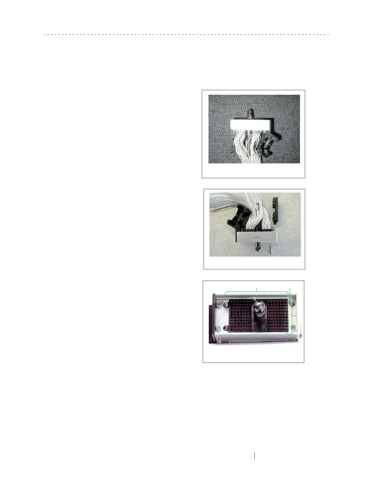
5
Remove the flat black end that is
opposite the strain relief by
loosening the screw from the
bottom. This will allow you more
room to work in the connector
(Figure 9-7).
6
U
se the pinout scheme in
Appendix C, "GSN Pinouts,”
to locate the correct contact
(Figure 9-8).
Figure 9-6. Let the wires hang loose
Figure 9-7. Remove the flat black end
Figure 9-8. Note the numbers
and letters marked on the connector
Numbers
Letters