8: Connectivities
87
Geodesic Sensor Net Technical Manual
S-MAN-200-GSNR-001 • January 31, 2007
Smart Nets
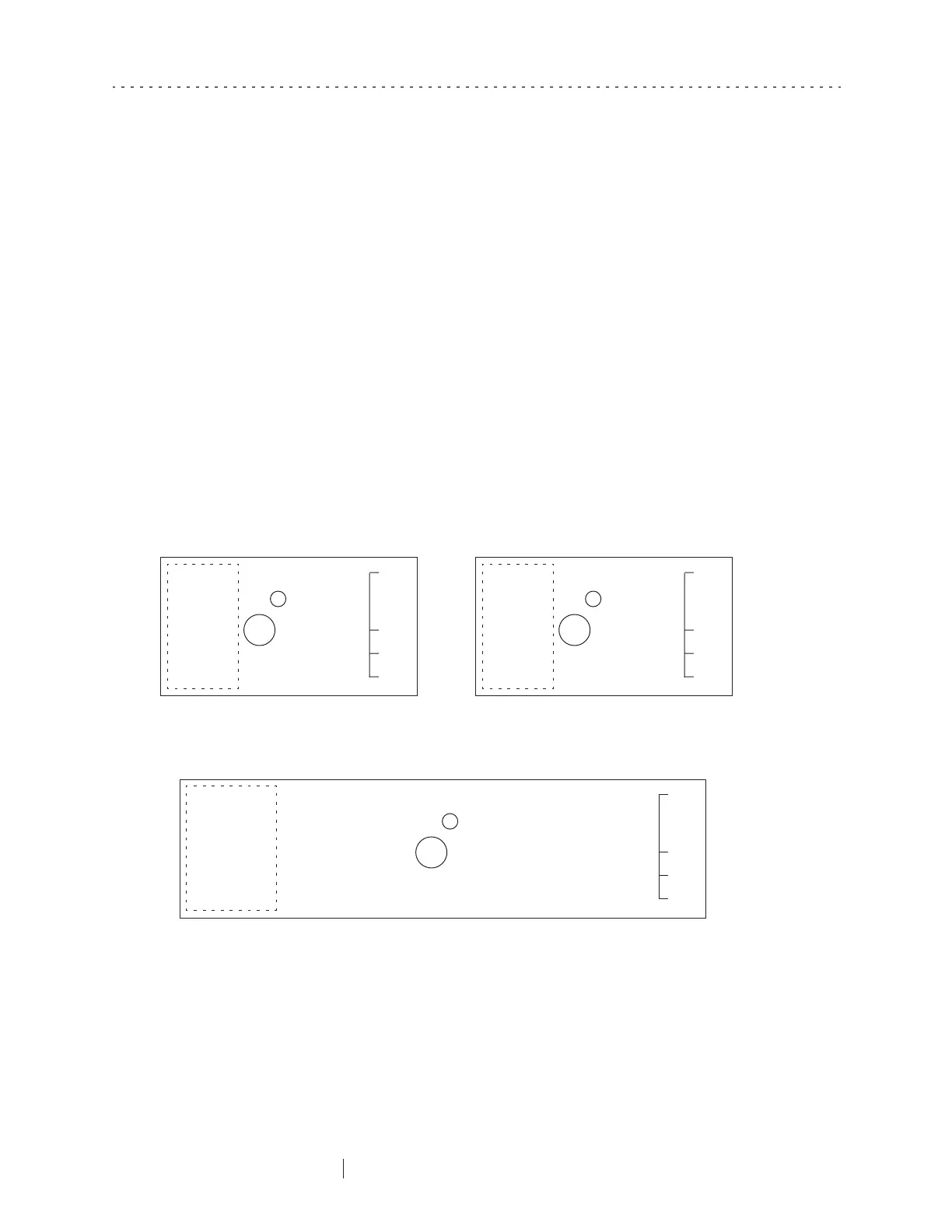
During manufacturing, factory settings are made at EGI using jumpers on each GSN,
such that each Net has a coded channel count and type. EGI’s EEG data-acquisition
software, Net Station, reads this identity via its interface to the amplifier and can
automatically choose a sensor layout that matches the connected Net. EGI calls this
technology “Smart Nets.” For details of the Smart Net coding, see Appendix C, "GSN
Pinouts,” and Figure 8-6.
Note: The 32-channel HCGSNs of the GES 120 and 140 do not use “Smart Net”
technology.
Figure 8-6. Schematic view of GSN connectors
Geodesic Sensor Net Smart Net Coding
1 2 3 4 5 6 7 8 9 10 11 12 13 14 15 16 17 18 19 20 21 22 23 24 25 26 27 28 29 30 31 32 33 34 35
A
B
C
D
E
F
G
H
J
K
GND
AMP0
AMP1
AMP2
????
GSN0
GSN1
GSN2
GSN3
????
1 2 3 4 5 6 7 8 9 10 11 12 13 14 15 16 17 18 19
A
B
C
D
E
F
G
H
J
K
GND
AMP0
AMP1
AMP2
????
GSN0
GSN1
GSN2
GSN3
????
64 channel
256 channel
Note: Smart
Net pins are
located in
column 19
Note: Smart Net
pins are located
in column 32
1 2 3 4 5 6 7 8 9 10 11 12 13 14 15 16 17 18 19
A
B
C
D
E
F
G
H
J
K
GND
AMP0
AMP1
AMP2
????
GSN0
GSN1
GSN2
GSN3
????
128 channel
Note: Smart
Net pins are
located in
column 19