6: Applying the GSN
65
Geodesic Sensor Net Technical Manual
S-MAN-200-GSNR-001 • January 31, 2007
Figure 6-7; cardinal sensors are located at the vertices of the major triangles
and used in EGI’s Geodesic Photogrammetry System).
° Locate the back of the Net (this is where the wires exit the sensor array for the
HCGSN).
2
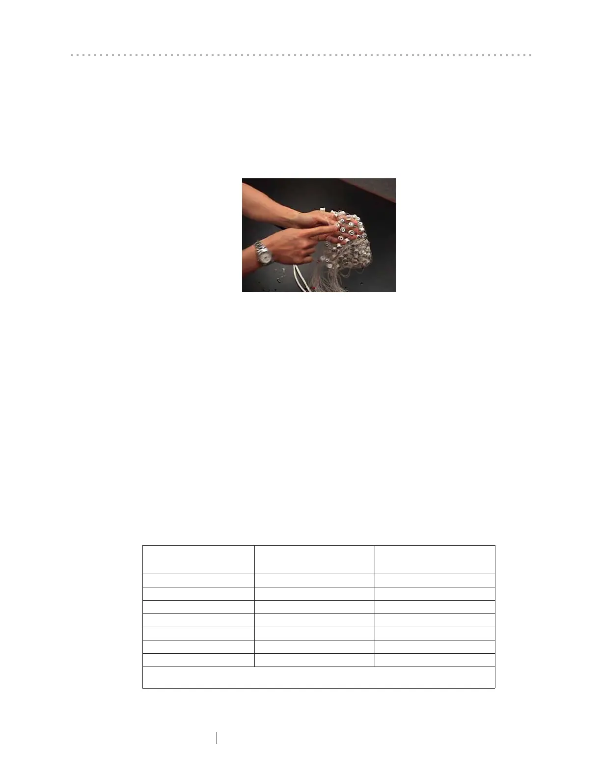
Place your hands
underneath
the face straps and hold the GSN so that you are
touching the underside of the Net (in other words, your hands are in contact
with the pedestal feet).
3
Locate the nasion sensor (which is colored in both the GSN 200 and the
HCGSN), which is situated on a multistring
perimeter band
, one of the strongest
parts of the Net.
4
On either side of the nasion, count two electrodes out and hook your thumbs
underneath the strings of the perimeter band (Figure 6-8). (Note: if you are
applying a 256-channel Net, you should count
three
electrodes out.) Table 6-1
lists the correct thumb positions for various sensor densities.
Figure 6-7. The HCGSN features red pedestals for the nasion and cardinal points
Table 6-1. Thumb placement when applying Net
GSN number of channels
Left thumb
between sensor numbers:
Right thumb
between sensor numbers:
32-channel HCGSN unnumbered sensors* unnumbered sensors*
64-channel HCGSN 17 and unnumbered sensor** 1 and unnumbered sensor**
128-channel HCGSN 1 and 8 25 and 32
256-channel HCGSN 1 and 10 46 and 54
64-channel GSN 200 1 and 60 14 and 19
128-channel GSN 200 1 and 8 26 and 33
256-channel GSN 200 1 and 10 45 and 53
* Figure B-1 on page 123 shows proper thumb placement for the 32-channel HCGSN.
** Figure B-2 on page 124 shows proper thumb placement for the 64-channel HCGSN.