Instruction manual Design and function
51
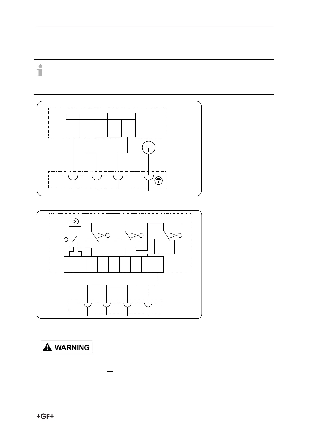
5.4 Wiring diagram EA25/45/120/250
Standard actuators: Provided with DIN-Plugs EXW. Follow diagrams below.
cUL marked actuators: Provided with cable glands. Connect open wired
directly to Terminals 1-N.
Connection of the voltage supply for positions OPEN, CLOSE and MIDDLE
5 6 7 8 9
1011
1213
Connection
terminals
Ready to
operate
close middleopen
green
Connector
blackwhitered
COM
Relay ratings:
Relays: Max. 6A @
either 230VAC or
24VDC
Caution: Do not mix
24VDC and 230VAC!
Apply only one
voltage-level!
NO NO NC NO NC COM NO NC
1 2 3 4
Connection of position feedback for positions OPEN, CLOSE (MIDDLE optional)
Do not connect mixed voltage potentials or voltage sources on the feedback relays.
Either connects 230VAC or 24VDC the feedback relays. Do not connect 230VAC and
24VDC at the same time. Also ensure the voltage is supplied from one single source
to all relay contacts at all times.
1
2 3 4
N
connection
terminals
green/yellow
connect
or
blackredg
reen
1 2 3
open close
midd
le
permanent
PE – P
rotective
Earth IEC60364