Instruction manual Installation
55
Feedback relays
Mono-stable change-over contacts
Either max 6A @ 230VAC or 24VDC, no mixed voltage potentials
allowed!
Recommended
connecting cable
AWG 18-16, UL/cUL AWM 4486 min. 125°C 1000V , outside diameter
8-13mm (cable glands), 4-9mm (DIN-connectors)
Allowable humidity
Max. 90 % relative humidity, non condensing
Housing material
Housing: PP-GF (POLYFLAM, RPP 4225 CS1)
Inspection glass: Udel P-1700 (CL2611)
7 Installation
If a complete valve is supplied, no mounting activities and adjustments are required. The actuator
can directly be put into operation, see Chapter “Commissioning” . When assembled by the
customer, the actuator must be assembled, connected, and, if necessary, adjusted.
7.1 Installing the actuator with valve
The actuators have a standard ISO 5211 interface, and can therefore be mounted on all valves
that are provided with this interface and the appropriate torques. The assembly using valves
from GF Piping Systems with suitable coupling piece and adapter is possible in accordance
with the following table:
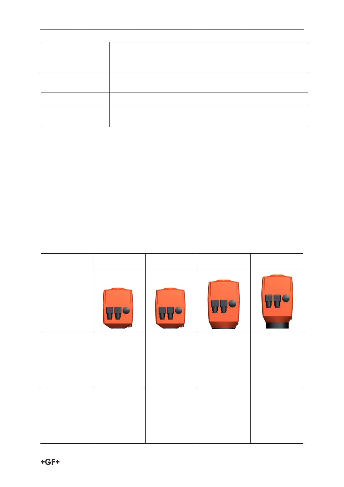
EA 25 EA 45 EA 120 EA 250
2-way ball
valve to DN 50
e. g. ball valve
type 546 Pro
DN10-DN50 /
3/8 – 2 inch
- - -
2-way ball
valve to DN 100
e. g. ball valve
type 546 Pro
DN65-DN100 / 2
½ - 4 inch
-
(DN65)
(DN80/100)
-