Installation Instruction manual
58
7.1.2 Preparation and assembly
In addition to this manual, please also follow the specifications of the valve manufacturer.
Before installation, compare the technical data of the actuator with those of the control
and the valve. Only install the actuator if the data match.
Before installation, check plugs and terminals for possible damage.
Make sure that no damaged parts are used.
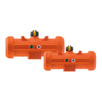
Mount the actuator on the valve, see assembly instructions of the respective manual valve.
If the actuator for the system requires protection class IP67, implement the following
measures:
- Use cable glands.
- Fit the actuator vertically.
Req. external breakers on all live wires:
Rated Current: max. 16A,
Trip Curve: C
Standards Compliance: cUL489, CSA C22.2 No. 5.1, IEC 60947-2
Fuse / circuit breaker must be positioned in Phases (P) and Neutral (N).
7.1.3 Connecting the actuator
Danger of injury and/or damage to property.
Make sure that 24 V devices are only connected to voltages that meet the requirements
of a safety extra low voltage circuit (SELV).
Damage to the actuator by short circuit or corrosion!
Moisture and/or dirt in the actuator.
Make sure that no water enters the actuator.
Mount the cable routing, so it does not point upwards.
Requirements
Recommended connecting cable specifications:
AWG 18-16, min. 125°C, 1000V, cUL AWM Style 4486, outside diameter 8-13mm
(cable glands), 4-9mm (DIN-connectors).
Sizing & position and marking of the fuse / circuit breaker (voltage supply side,
110-230VAC):
Req. external breakers on all live wires: Rated Current: max. 16A, Trip Curve: C,
Standards Compliance: cUL489, CSA C22.2 No. 5.1, IEC 60947-2, Fuse / circuit
breaker must be positioned in Phase (P) and Neutral (N).