Integration
333587B 69
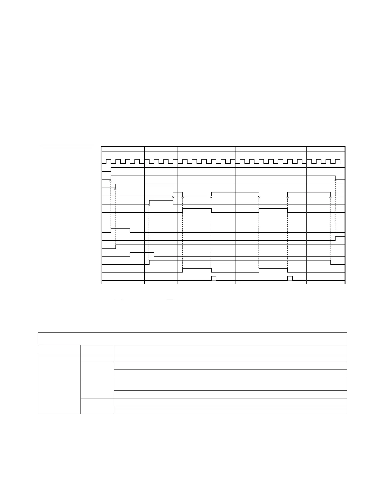
Job Cycle Timing Diagram
Timing recommendations:
• Use discrete signals when possible, especially for the Go signal. Use optional I/O Cable 122029 for discrete
signals.
• Use a 50 ms delay between bits.
Automation Control Ready in the following diagram represents:
• Pump is active
• No active alarms
• ADM is in Remote mode
Automation Inputs (E-Flo iQ Outputs)
Heart Beat (1Hz)
Automation Control Ready
System Active
+PLC Lockout/Control Active
System Ready to Dispense
Ƒ3UHFKDUJH'HFKDUJH$FWLYH
Dispense In Process
Automation Outputs (E-Flo iQ Inputs)
* Enable System/Remote Start Request
^System Disable Request
¸6W\OH(QDEOH
¸*R6LJQDODVUHTXLUHG
Á¸'LVSHQVH&RPSOHWH
Job Cycle Timing Diagram
Pre Job Cycle Pre-charge/De-charge Dispense 1 Dispense 2,3… Post Job Cycle
^ Disabling the pumps(s) is optional. Does not diable heat.
Notes:
* Can be enabled at the same time.
+ Can only
be used through the fieldbus; and must be used to operate the system.
Ƒ3UHFKDUJHZLOORQO\EHDFWLYHZKHQWKHUHLVDVHWSRLQWVWRUHGLQWKHGLVSOD\RUSDVVHGRYHUWKH&*0
¸7KHVLJQDOVRXUFHFDQEHHLWKHUGLVFUHWHRUILHOGEXV*RWR6W\OH'HILQLWLRQVWKHQQDYLJDWHWRWR6W\OH,QWHJUDWLRQ6HWXSVFUHHQGHILQHWKHVRXUFH
‡ The dispense complete is optional. This bit summates the volume dispensed any time it is triggered. Dropping the style strobe will also summate the volume dispensed.
CGM I/O Sequence
Function Sequence Description
Pre-Job Cycle
1
Check that Heartbeat is toggling ON and OFF at 1Hz.
2
Check that System Active bit is ON.
If System Active bit is OFF, Turn ON System Enable bit.
3
Check that Automation Control Ready bit is ON. Note: Active only when there are no active
alarms, the system is enabled and the system is in REMOTE mode.
If Automation Control Ready bit is ON, Turn ON PLC Lockout bit.
4
Check that PLC Lockout bit is ON.
If PLC Lockout/Control bit is ON, Enter desired Style Number (16bit integer).
 Loading...