Integration
333587B 71
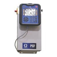
Communications Gateway Module (CGM)
Overview
The Communications Gateway Module (CGM) provides
a control link between the E-Flo iQ system and a
selected fieldbus. This provides the means for report
monitoring and control by external automation systems.
NOTE: The following system network configuration files
are available at help.graco.com.
• EDS file: DeviceNet or EtherNet/IP fieldbus
networks
• GSD file: PROFIBUS fieldbus networks
• GSDML: PROFINET fieldbus networks
NOTE: See the Supply System Communications
Gateway Module Installation Kit manual for CGM
installation. See Related Manuals on page 3.
E-Flo iQ and PLC Connection Setup
Verify that the PLC parameters are set up correctly, see
the Gateway Map table.
NOTE: If the PLC connection parameters are not setup
correctly, the connection between the E-Flo iQ and PLC
will not be made.
Available Internal Data
Unless stated otherwise, bytes are stored in each
instance in little endian order (byte order within instance:
most significant to least significant).
NOTE: Automation Outputs can be monitored by the
corresponding Automation Inputs to verify that the E-Flo
iQ received the data.
See the Automation Outputs on page 72 and the
Automation Inputs on page 76.
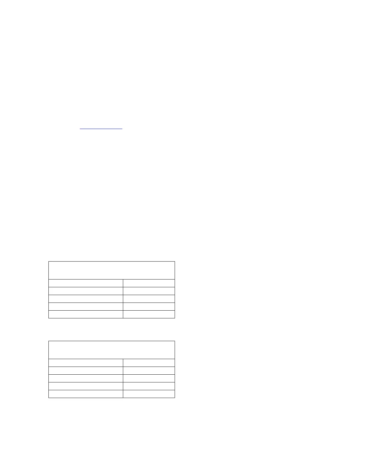
Gateway Map: 18A925 for E-Flo iQ Ram
Map name: E-Flo_iQ_Pico
Comm. Format Data-SINT
Input Assembly Instance: 100
Input Instance Size: 2
Output Assembly Instance: 150
Output Instance Size: 10
Gateway Map: 18A915
E-Flo iQ Advance Map
Comm. Format Data-SINT
Input Assembly Instance: 100
Input Instance Size: 78
Output Assembly Instance: 150
Output Instance Size: 32