Typical Installation
3A8572B 11
Typical Installation
General Information
Typical installations are shown in FIG. 3 and FIG. 4. The
figures are only guides for selecting and installing
system components. Contact your local distributor for
assistance in planning a system to suit your needs.
Always use Genuine Graco Parts and accessories. Be
sure all accessories are adequately sized and
pressure-rated to meet the requirements of the system.
Reference letters in the text, for example, (A), refer to
the callouts in the figures.
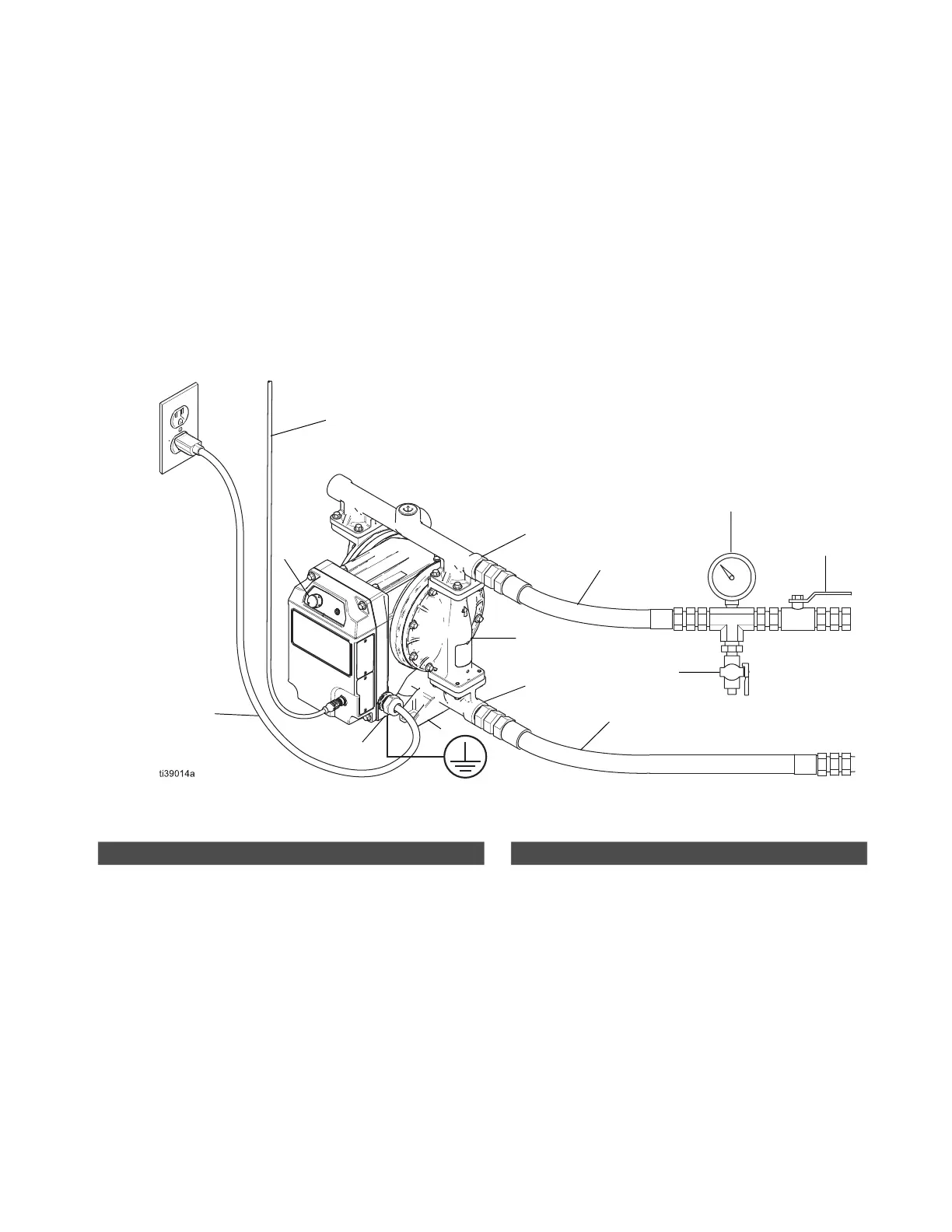
Typical Installation for Models in Ordinary Locations
FIG. 3: Typical Installation for Models in Ordinary Locations (cord and plug connection) (i30 (QTC) model shown)
A
B
C
D
E
F
G
H
J
M
N
K
L
Pump Components
A
♦
Power cord
B Fluid inlet port
C Fluid outlet port
D Mounting feet
E Ground fastener
K Fluid output control knob
L
▼
Diaphragm access ports (not shown)
♦
Connect to a circuit with a main electrical disconnect. Install
a branch circuit protective device in each ungrounded
phase. Follow local codes and regulations.
▼
See Install Monitoring Accessories, page 14, or Install
Fluid Leak Line Accessories, page 14.
Accessories (Not Supplied)
F* Conductive, flexible fluid supply line
G* Fluid drain valve
H Fluid shutoff valve
J* Conductive, flexible fluid outlet line
M Fluid pressure gauge
N I/O Cable
* Required, not supplied.