Electrical Connections and Wiring
20 3A8572B
I/O Pin Connection
For models in Ordinary Locations only.
NOTE: All I/O connectors are capable of 30 VDC (volts
of direct current) and are reverse-polarity protected.
For wiring, see Equivalent Electrical Circuits for I/O
Pin Connection, page 21.
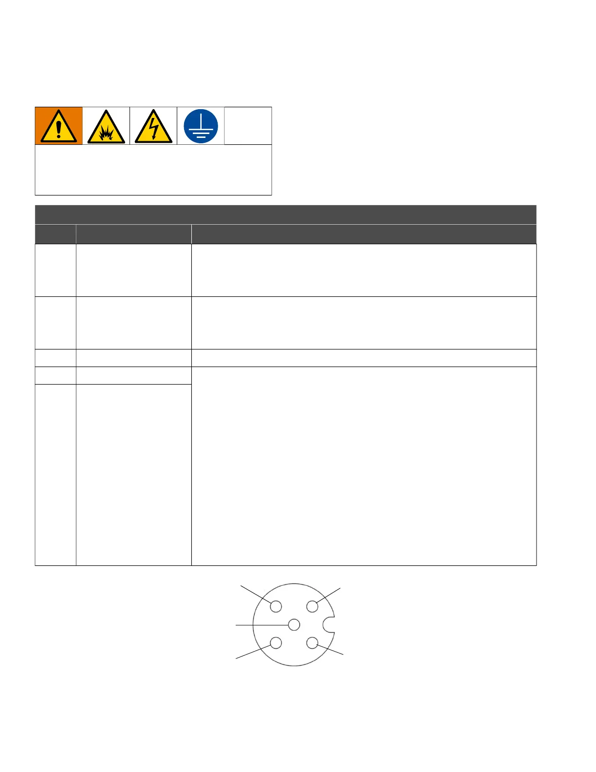
FIG. 11: M12, 5-pin Connector for Models in Ordinary Locations
To avoid injury from fire, explosion, or electric
shock, all electrical wiring must be done by a
qualified electrician and comply with all local codes
and regulations.
I/O Connector Pinout (for Models in Ordinary Locations only)
Pin Connector Type Description
Pin 1 Digital Input Digital input has an internal 5 VDC pull-up for dry-contact or current-sinking
circuits. Digital input is internally clamped for push-pull outputs. Release or
drive the input high to stop the equipment from running. Pull the input low to
re-enable the equipment.
Pin 2 Digital Output
(Equipment Running)
Digital output is current-sinking with a current capacity up to 100 mA. Digital
output is internally clamped for driving large inductive loads. The output is
automatically pulled low when the equipment is running and automatically
released when the equipment is not running.
Pin 3 GND/Common Earth ground, common connection.
Pin 4 Analog Input, Positive Analog inputs are 4–20 mA current-controlled. When the analog input is
connected and driving current, the equipment disables the control knob (K)
and uses the analog input to control the speed and pressure of the
equipment. The control knob (K) can still be used to shut off the equipment by
turning the knob to off (0). To re-enable the equipment at the speed and
pressure commanded by the analog input, turn the control knob up
(clockwise).
To disable the analog input control and enable the control knob (K):
1. Shut down the equipment. See Shut Down the Equipment, page 24.
Ensure the LED indicator is off (no light).
2. Disconnect power to the system.
3. Disconnect the analog input (Pin 4, Pin 5).
4. Connect the unit to a power source to turn on the equipment and enable
the control knob (K) on the equipment.
Pin 5 Analog Input, Negative
Pin 1
Pin 2
Pin 3
Pin 4
Pin 5