Typical Installation
12 3A8572B
Typical Installation for Models in Explosive Atmospheres or
Hazardous (Classified) Locations
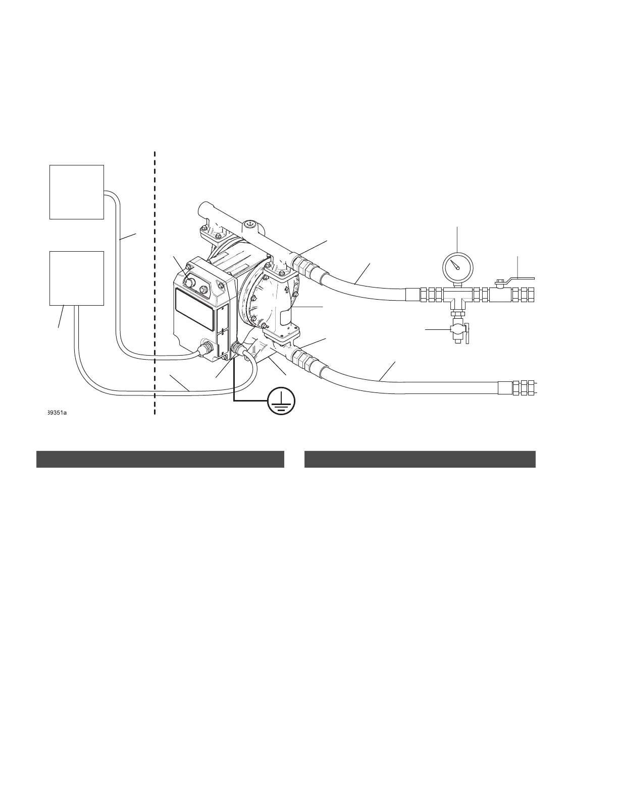
FIG. 4: Typical Installation for Models in Explosive Atmospheres or Hazardous (Classified) Locations (hard wired for
permanent connection) (i30 (QTC) model shown)
\
A
B
C
D
E
F
G
H
J
M
N
K
Explosive Atmosphere or Hazardous (Classified) Location
Ordinary Location
AA
L
Pump Components
A
♦
Power cable
B Fluid inlet port
C Fluid outlet port
D Mounting feet
E Ground fastener
K Fluid output control knob
L
▼
Diaphragm access ports (not shown). Diaphragm
access ports must not be open in hazardous locations.
Ports must have installed either plugs 128658 (as
shipped from the factory), or leak sensor kit 25F109.
♦
Connect to a circuit with a main electrical disconnect. Install
a branch circuit protective device in each ungrounded
phase. Follow local codes and regulations.
▼
See Install Monitoring Accessories, page 14, or Install
Fluid Leak Line Accessories, page 14.
Accessories (Not Supplied)
F* Conductive, flexible fluid supply line
G* Fluid drain valve
H Fluid shutoff valve
J* Conductive, flexible fluid outlet line
M Fluid pressure gauge
N*
‡
I/O Cable
AA Electrical disconnect
* Required, not supplied.
‡
I/O cable kits are available (purchase separately). See
your related motor manual. See Related Manuals,
page 2.