Electrical Connections and Wiring
18 3A8572B
Wire Power Cables
For models in Explosive Atmospheres or Hazardous
(Classified) Locations only.
To connect an Explosive Atmospheres or Hazardous
(Classified) Locations model to a power source,
complete one of the following:
• Hard wire the equipment to a power source.
• Supply a plug, socket, and interlocking device that
meets the requirements of EN 60079-0 or UL 674.
NOTE: See Required Power and Plugs, page 17, for
power requirements. Install a branch circuit protective
device in each ungrounded phase.
A 15 ft (4.6 m) cable (either 3-conductor or 4-conductor)
is provided with models for Explosive Atmospheres or
Hazardous (Classified) Locations. Connect the cable
directly to a panel with branch circuit protection and an
electrical disconnect per local codes and regulations. If
additional length of cable is required, connect additional
cable through a junction box. Use the following table to
select the minimum cable wire gauge based on length:
NOTE: Ensure that the electrical disconnect (AA) is shut
off and locked out before wiring. See F
IG. 8.
FIG. 8: Electrical Disconnect
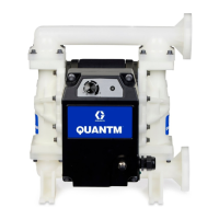
Wire Single-Phase Models
For models in Explosive Atmospheres or Hazardous
(Classified) Locations only. See F
IG. 9.
1. FC6 motors: Connect the black wire to Line 1 (L1,
black).
FC4 motors: Connect the brown wire to Line 1 (L1,
brown).
2. FC6 motors: Connect the white wire to Neutral
(L2/N, white).
FC4 motors: Connect the blue wire to Line 2 (L2/N,
blue).
3. Connect the ground wire (green) to a true earth
ground.
FIG. 9: Wiring for Single-Phase Models
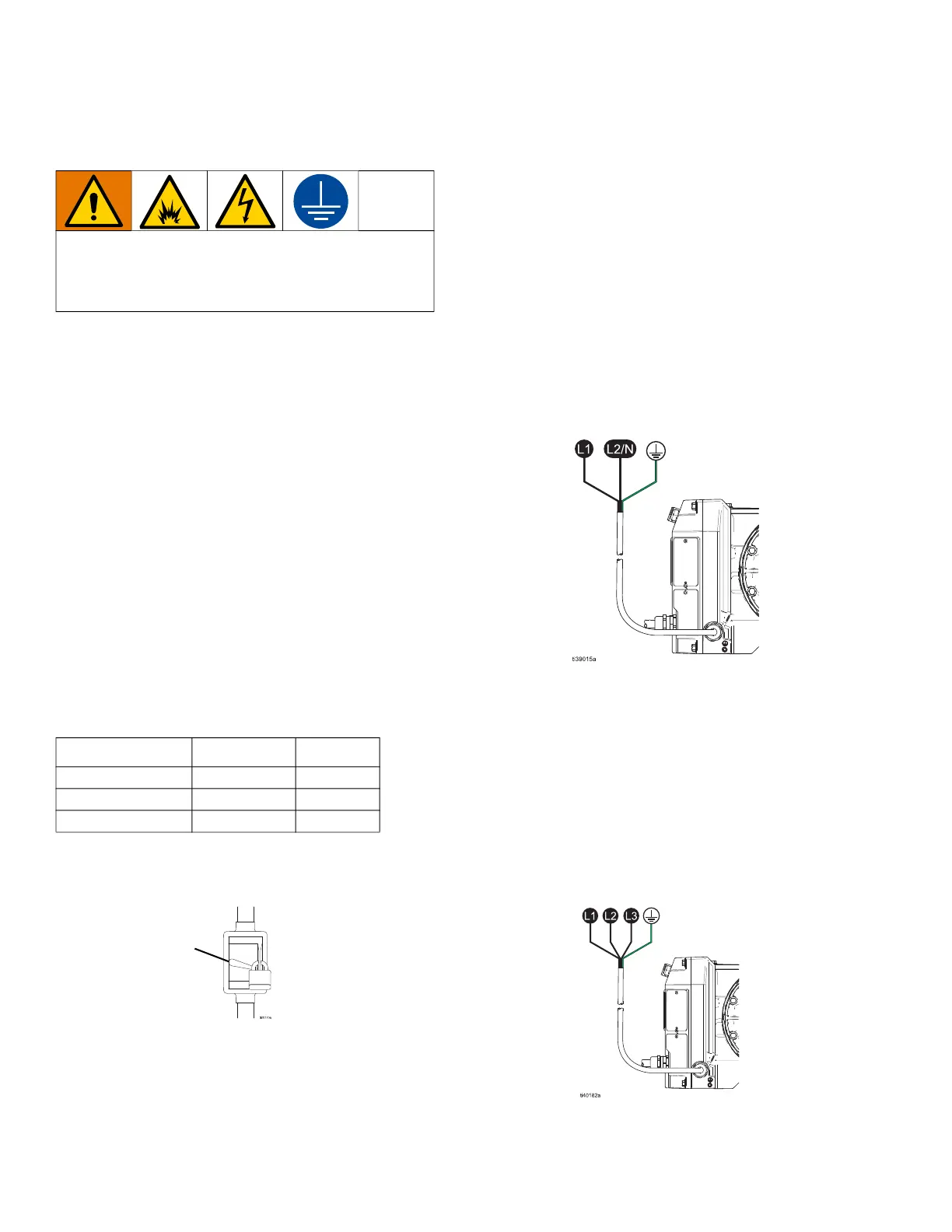
Wire 3-Phase Models
For models in Explosive Atmospheres or Hazardous
(Classified) Locations only. See F
IG. 10.
1. Connect the black wire to Line 1 (black, L1).
2. Connect the white wire to Line 2 (white, L2).
3. Connect the red wire to Line 3 (red, L3).
4. Connect the ground wire (green) to a true earth
ground.
FIG. 10: Wiring for 3-Phase Models
To avoid injury from fire, explosion, or electric
shock, all electrical wiring must be done by a
qualified electrician and comply with all local codes
and regulations.
Length Gauge
mm
2
50 ft (15.2 m) 12 AWG 3.3
100 ft (30.4 m) 10 AWG 5.3
200 ft (61 m) 8 AWG 13.3
AA