Electrical Connections and Wiring
3A8572B 17
Electrical Connections and Wiring
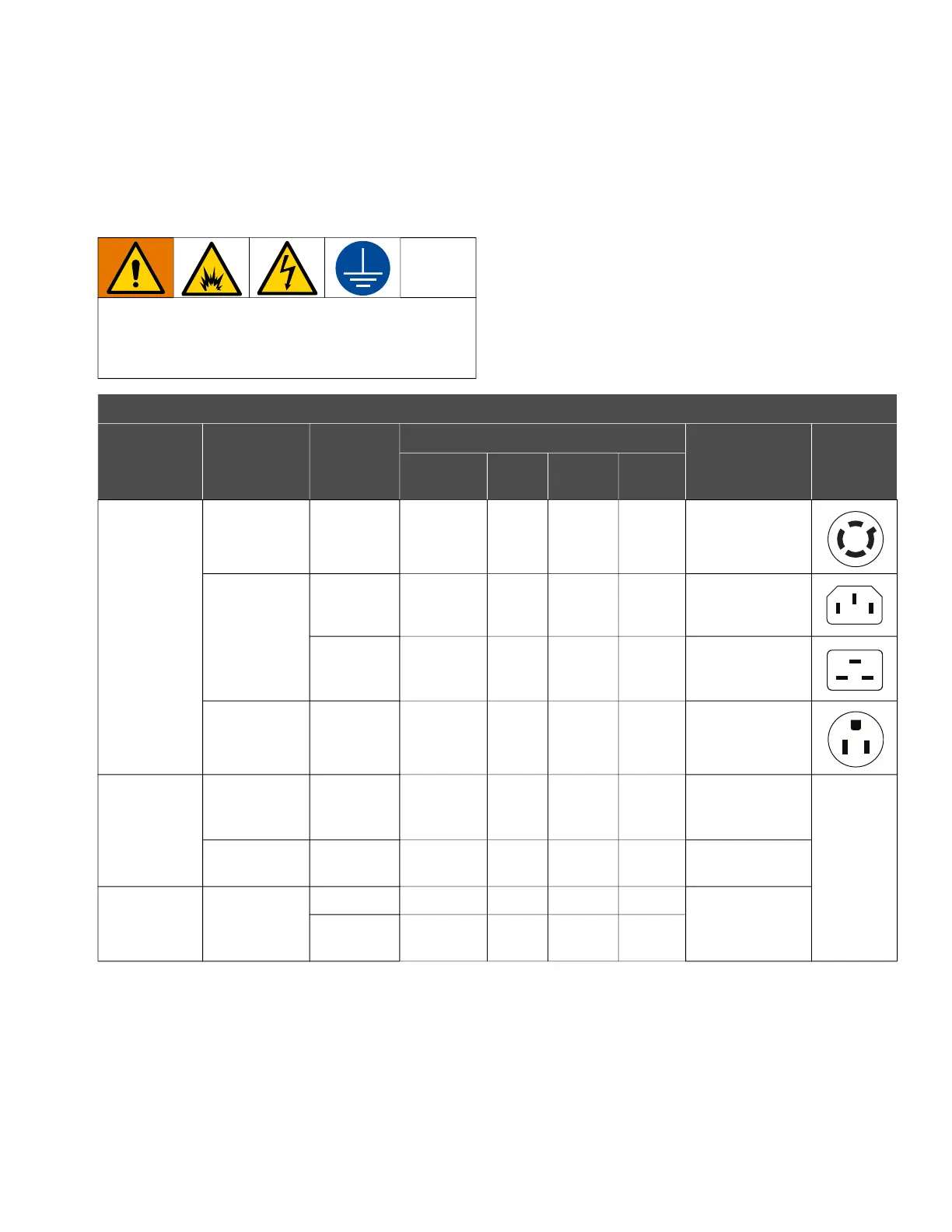
Required Power and Plugs
NOTE: For equipment provided with a cable and flying
leads (no plug), install a main electrical disconnect per
local codes and regulations.
NOTE: Use adapters as needed. Follow local codes
and regulations.
To avoid injury from fire, explosion, or electric
shock, all electrical wiring must be done by a
qualified electrician and comply with all local codes
and regulations.
Required Power and Plugs
Location
Motor
Configuration
Code*
Model
Power Requirements
Cord/Cable
Termination
Plug
Input
Voltage
Phase
‡
Hertz Current
Ordinary
Locations
FC1
i80 (QTD),
i120 (QTE)
200–240 V 3 50/60 Hz 7.5 A
NEMA L15-20
Plug
FC2
i30 (QTC)
200–240 V 1 50/60 Hz 10 A
IEC 60320-C14
Plug
✦
i80 (QTD),
i120 (QTE)
200–240 V 1 50/60 Hz 15 A
IEC 60320-C20
Plug
✦
FC5 i30 (QTC)
100–120 V 1 50/60 Hz 12 A
NEMA 5-15 Plug
Hazardous
(Classified)
Locations
FC3
i30 (QTC),
i80 (QTD),
i120 (QTE)
200–240 V 3 50/60 Hz 7.5 A
Flying Leads, see
F
IG. 10
For
permanent
connection
■
FC6 i30 (QTC)
100–120 V 1 50/60 Hz 12 A
Flying Leads, see
F
IG. 9
Explosive
Atmospheres
FC4
i30 (QTC)
200–240 V 1 50/60 Hz 10 A
Flying Leads, see
F
IG. 9
i80 (QTD),
i120 (QTE)
200–240 V 1 50/60 Hz 15 A
* See Configuration Matrix, starting on page 7, for detailed descriptions.
‡
Connect to a circuit with a main electrical disconnect. Install a branch circuit protective device in each ungrounded phase.
Follow local codes and regulations.
■
See Wire Power Cables, page 18.
✦
Adapters are available (purchase separately). See Adapters for Plugs and Cables, page 19.