Troubleshooting
4.Checkfunctionalityofthedirectionalvalve
(207).
a.Conrmthatthedirectionalvalvecable
isconnectedproperlyfromHCMport15
tothedirectionalvalvebody(207)and
isnotdamaged.Inspectwiringinside
thecoverofthedirectionalvalve.See
ElectricalSchematics,page105.
b.Duringoperation,thedirectionindicator
lightsonthedirectionalvalvebody(207)
shouldswitchonbasedonthevalvethat
isopen.
c.Turnonthemotorandstallthepumpsat
thelowestpressuresetting(compensator
knobturnedfullycounter-clockwise).
ThepumpwilltravelineithertheAor
Bdirectionuntilthepressuresettingis
reached.
d.Identifythesolenoidthatisoperating
byviewingthedirectionindicatorlights
onthecoverofthedirectionalvalve
(207).Measurevoltageacrossthe
associatedterminalstodetermineif
propervoltageisreachingthevalve
(approximately200to240VAC).See
ElectricalSchematics,page105,and
thetablebelow,toidentifytheproper
terminalstomeasureacross.
e.Triggereachproximityswitch(211)with
theshaftofascrewdriver,conrming
eachsolenoidwithinthedirectionalvalve
(207)operatesasdescribedintable
below.
f.Ifoneorbothsidesarenotoperating
properly,accordingtothetable,rst
reconrmwiringtodirectionalvalve
(207)perElectricalSchematics,page105,
thenreplacedirectionalvalve(207).
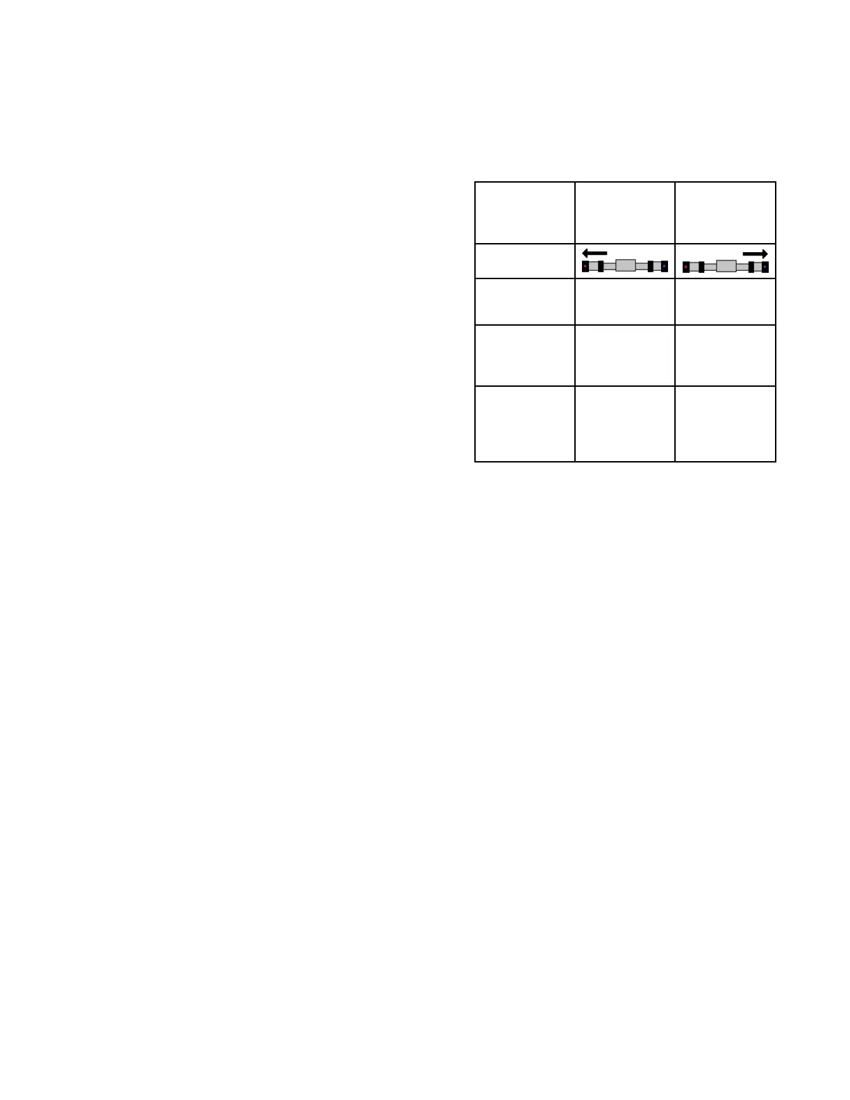
For For
For
given given
given
pump pump
pump
movement movement
movement
direction: direction:
direction:
Pump Pump
Pump
driving driving
driving
left left
left
(toward (toward
(toward
park park
park
position) position)
position)
Pump Pump
Pump
driving driving
driving
right right
right
(away (away
(away
from from
from
park park
park
position) position)
position)
ADM
indicates
Indicatorlight
ondirectional
valvecover
Leftarrow,
labeled“b”
Rightarrow,
labeled“a”
Last
proximity
switch
triggered
Rightside
proximity
switch
Leftside
proximity
switch
Terminalsin
directional
valve
energized
Terminals
associated
withredand
orangewires
Terminals
associated
withblack
andwhite
wires
NOTE: NOTE:
NOTE:
Fordiagnosticpurposes,itispossible
tomanuallyoverridethedirectionalvalve
byusingasmallscrewdrivertodepressthe
buttoninthecenterofeitherdirectional
valveendcap.Depressingthebuttoninthe
rightendcapshouldcausethepumpto
traveltotheright.Depressingtheleftbutton
shouldcausethepumptotraveltotheleft.
5.Ifyouhavedeterminedthatthecauseis
noneofthepreviouspossiblecauses,check
foraloosepistonpackingretainingbolt.
Thiscausesthepistontocontacttheinner
faceofthepumpinletangebeforethe
switchingplateactivatestheproximity
switch.Shutdowntheunitanddisassemble
theappropriatepumpforrepair.
Following Following
Following
step step
step
1, 1,
1,
if if
if
the the
the
proximity proximity
proximity
switch switch
switch
indicating indicating
indicating
lights lights
lights
do do
do
not not
not
light: light:
light:
6.Checkforlooseorfaultyproximity
switchcableorconnections.Conrmthe
connectionstotheproximityswitchesare
tightandinternallyfreefromoilandother
contaminates.
7.Swapthecablestotheproximityswitchesto
seeiftheproblemfollowstheswitchorisin
thecable.Replaceeitherthefailedswitch
orthecable.
8.ReplacetheHCM.SeeReplaceHCM,page73.
334946J
43
 Loading...


