Repair
Transformer Transformer
Transformer
Primary Primary
Primary
Check Check
Check
SeeElectricalSchematics,page105.
1.Checkwiresandtransformer:
a.SeeShutdown,page50.
b.ShutoffCB15.
c.Useanohmmetertotestforcontinuity
betweenterminals2and4ofCB15.If
thereisnocontinuity,checktransformer
andwiringbetweenCB15andTB31
locatedbehindthelowercover.Goto
step2.
2.ChecktransformerandTB31:
a.SeeShutdown,page50.
b.Removethelowercover.
c.Locatethetwosmaller(10AWG)
wires,labeled1and2,comingoutof
transformer.Tracethesewiresbackto
terminalblocksTB31.
d.Useanohmmetertotestforcontinuity
betweentwowires;thereshouldbe
continuity.
Transformer Transformer
Transformer
Secondary Secondary
Secondary
Check Check
Check
SeeElectricalSchematics,page105.
1.Checkwiresandtransformer:
a.SeeShutdown,page50.
b.Disconnect7pingreenconnectorfrom
TCM.
c.Useanohmmetertotestforcontinuity
betweenterminals6and7ontheTCM
7pingreenconnector.Thereshould
becontinuity.Ifthereisnocontinuity,
checktransformerandwiring.
d.Leave7pingreenconnector
disconnectedfromTCM.
2.Checktransformer:
a.Removelowercover.
b.Locatethetwolarger(6AWG)wires,
labeled3and4,comingoutof
transformer.Tracethesewiresback
toTB31.Useanohmmetertotestfor
continuitybetweentwotransformer
wiresinterminalblockTB31;there
shouldbecontinuity.
c.Reconnectthe7pingreenconnectorto
theTCM.
d.Applyincomingpowertosystem.
e.Toverifyvoltageonthesecondaryleads
ofthetransformer,measurebetween
thetransformerleadslabeled3and4
atTB31.Verifythetransformeroutput
voltageisapproximately37.5%ofthe
systemsupplyvoltageforH-30and
H-XP2systemsorapproximately50%
ofsystemsupplyvoltageforH-40,
H-50,andH-XP3.Forexample,with
a240VACsystemsupplyvoltagethe
transformeroutputvoltageforanH-30
orH-XP2wouldbe(.375x240V),or
approximately90V;foranH-40,H-50,
orH-XP3itwouldbe(.50x240V),or
approximately120V.
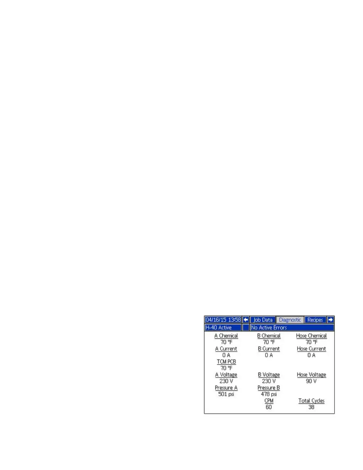
f.SeetheDiagnosticRunScreenon
theADM.TheDiagnosticRunScreen
displaysthetransformeroutputvoltage
(approximately90or120VAC)under
“HoseVoltage”.Thediagnosticscreen
willshowaHoseVoltageof“0”voltsif
thecircuitbreakerhasbeentrippedfor
theincomingpowertotheTCM.
NOTE: NOTE:
NOTE:
TheDiagnosticRunScreenis
disabledbydefaultandmustbeenabled
intheSetupscreens.SeetheOperation
manualforinstructions.
70
334946J
 Loading...


