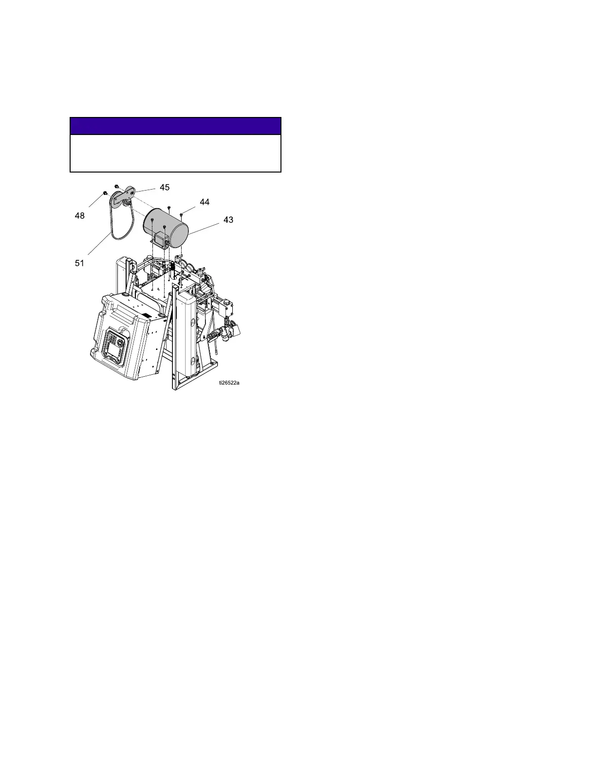
Repair
6.Removethebelt(51).See
ReplaceBelt,page61.Removethe
twopulleyscrews(48)andthebelt
tensioningassemblyfromthemotor.
NOTICE NOTICE
NOTICE
Topreventdamagetocables,donotcrush
orstrainanycablesnearthepointwhere
theframehalveshinge.
Figure5MotorandBeltAssembly
7.Removetheelectricmotorjunctionbox
cover(43).
8.Disconnectthemotorcables.See
ElectricalSchematics,page105.
9.Noteorlabelthewireconnections.Seethe
ElectricalSchematics,page105andthe
diagraminsidethemotorjunctionboxcover.
Themotormustoperatecounter-clockwise
whenlookingattheoutputshaft.
10.Removethemotor.
Installation Installation
Installation
1.Placethemotorontheunit.
2.Fastenthemotorwithbolts.
3.Connectthewires,usingwirenuts.See
ElectricalSchematics,page105,andthe
diagraminsidethemotorjunctionbox.
Note
For3–PhaseMotors,themotormust
rotatecounterclockwisewhenviewed
fromtheshaftend.Ifrotationis
incorrect,reversepowerleadsL1and
L2.FollowConnect Connect
Connect
Electrical Electrical
Electrical
Cord Cord
Cord
instructionsinthesystemoperation
manual.
4.Replacebracket(133)andthebeltand
heatercovers(131,132,134).
5.Raiseelectricalenclosureintothevertical
positionandensurewiresarenotpinched
betweentheframehalves.Replaceand
tightenbolts(3).
6.Openelectricalenclosure.ConnecttheA
sideheaterconnectortheTCM.
7.Securethesystemtooriginalmounting
location.
8.Returntoservice.
60
334946J
 Loading...


