GMV5 Home DC Inverter Multi VRF Units
180
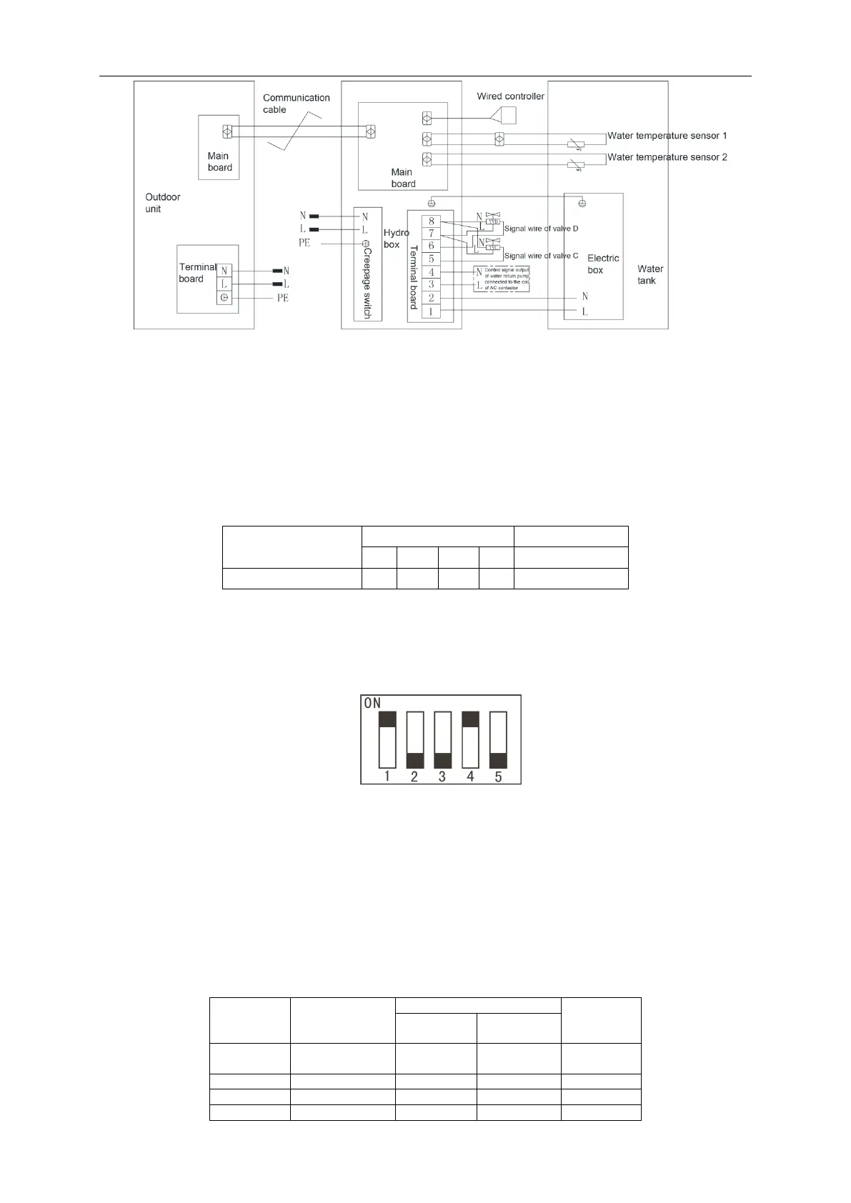
Note: The above wiring diagram is only for reference. Detailed content please refer to the
wiring diagram stuck inside the electric box of unit.
(2)Confirm DIP of mainboard
Confirm the S
1
and S
2
DIP switch on the main board of hydro box. S
1
DIP means capacity DIP
switch. S
2
DIP means function DIP.
Capacity DIP(S
1
) of Hydro Box
Capacity DIP switch S
1
is 5 bit. Please do not change it.
Note:
① DIP switch shall be set correctly and cannot be set in the middle position. When the
switch is set to ―ON‖, it means ―0‖; when the switch is set to the opposite direction of ―ON‖,
it means ―1‖.
Example: S
1
is as shown in the following figure:
② The black part is the bar for setting DIP.
(S2)Function DIP (S2) of hydro box
Note: Please set strictly according to actual situation of project.
Function DIP S2 of hydro box has 4 digits. ―1‖, ―2‖, ―3‖ and ―4‖ mean ―Gree water tank‖, ―floor
heater‖, ―solar power‖, ―self-made water tank‖ respectively. The DIP of each function is applicable:
setting to ―number‖ means this function is connected; setting to ―ON‖ means not connected. ―1‖
and ―2‖ must be set according to the actual situation of project. ―3‖ and ―4‖ cannot be changed,
otherwise the unit may occur temperature sensor error or cannot operate.
 Loading...