English (GB)
13
6.4.2 Type key
7. Control functions
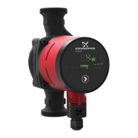
7.1 Elements on the operating panel
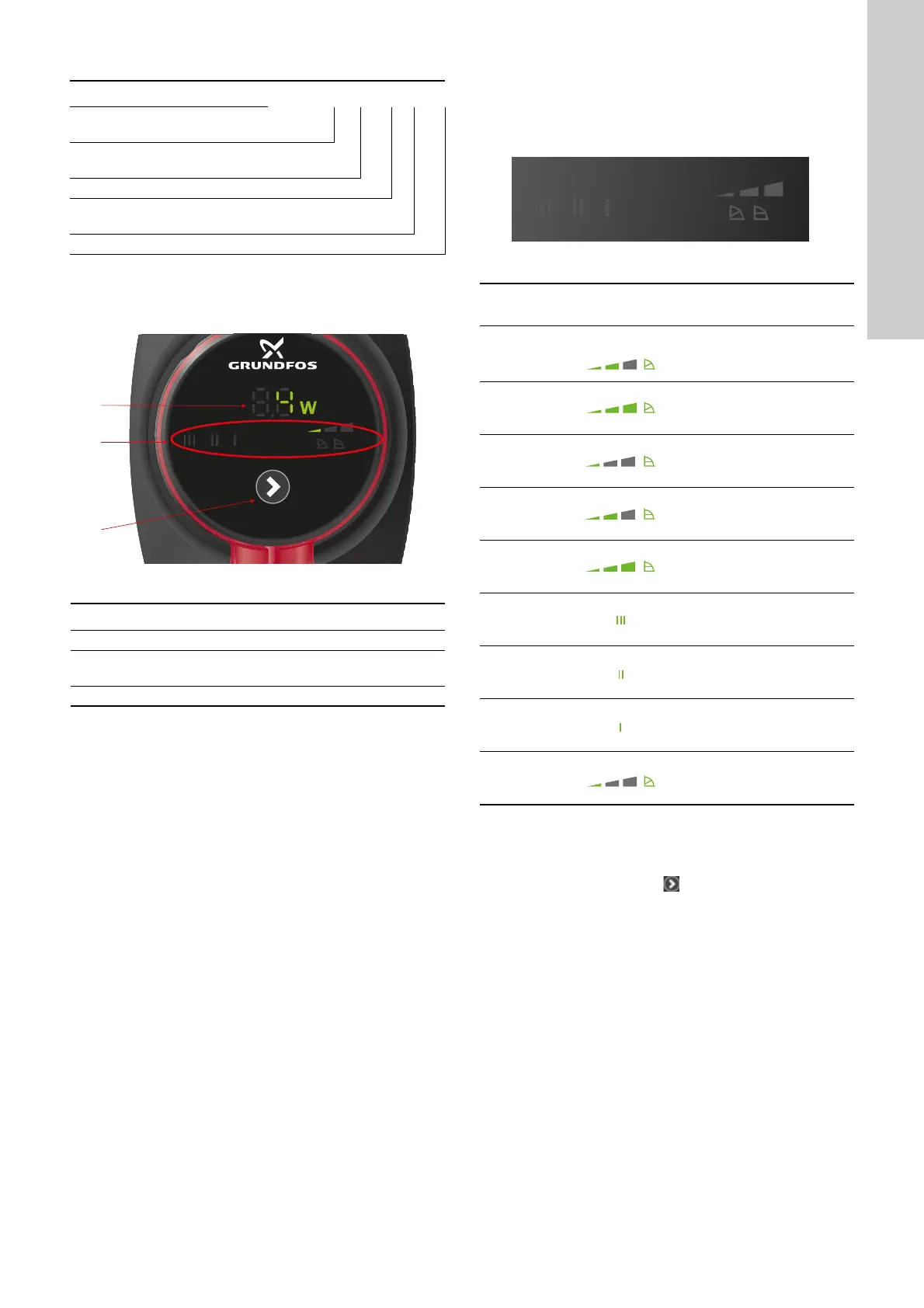
Fig. 14 Operating panel
7.2 Display
The display (1) is on when you have switched on the power
supply.
The display shows the actual pump power consumption in watt.
If the pump impeller is rotated, for example when filling the pump
with water, sufficient energy can be generated to light up the
display even if the power supply has been switched off.
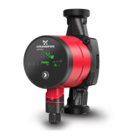
7.3 Light fields indicating the pump setting
The pump has nine performance settings which you can select
with the button (5). See fig. 14.
The pump setting is indicated by nine light fields in the display.
See fig. 15.
Fig. 15 Nine light fields
For information about the function of the settings, see section
7.5 Control modes.
7.4 Button for selection of pump setting
Every time you press the button , the pump setting is changed.
See fig. 14, pos. 5.
A cycle is nine button presses. See section 7.3 Light fields
indicating the pump setting.
Example ALPHA1 25 -40 N 180
Pump type
[ ]: Standard version
Nominal diameter (DN) of inlet and outlet
ports [mm]
Maximum head [dm]
[ ]: Cast-iron pump housing
N: Stainless-steel pump housing
Port-to-port length [mm]
TM06 9101 4317
Pos. Description
1 Display showing the actual power consumption in watt.
2
Light fields indicating the pump setting.
See section 7.3 Light fields indicating the pump setting.
3 Button for selection of pump setting.
TM06 9100 4317
Button
presses
Active light
fields
Description
0
Factory setting
Intermediate
proportional-pressure curve,
PP2
1
Highest
proportional-pressure curve,
PP3
2
Lowest constant-pressure
curve, CP1
3
Intermediate
constant-pressure curve,
CP2
4
Highest constant-pressure
curve, CP3
5
Constant curve/constant
speed III
6
Constant curve/constant
speed II
7
Constant curve/constant
speed I
8
Lowest proportional-pressure
curve, PP1