English (GB)
17
6. Electrical connections
Make sure that the pump is suitable for the electricity supply on
which it will be used.
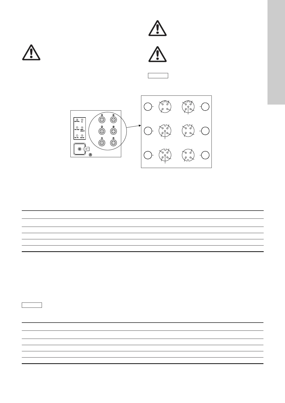
6.1 Connecting the signal lines for DDI 222
Fig. 16 DDI 222 connection diagram
6.1.1 Diaphragm leakage signal / (pressure sensor - Flow Monitor)
Socket 1
For diaphragm leakage signal (MBS) and/or pressure sensor (Flow Monitor pump option).
The diaphragm leakage signal and pressure sensor are pre-assembled with an M12 plug for socket 1.
• Connect the cables according to the table below.
6.1.2 Current output / Flow Monitor (pressure sensor)
Socket 2
For pressure sensor for Flow Monitor option.
The pressure sensor is supplied ready-made with M12 plug for socket 2 or socket 1.
The current output indicates the current dosing flow and can be weighted independently of the selected operating mode.
See section
9.6.4 Weighting of current input/output.
Warning
Electrical connections must only be carried out by
qualified personnel!
Disconnect the power supply before connecting the
power supply cable and the relay contacts!
Observe the local safety regulations!
Warning
The pump housing must only be opened by
personnel authorised by Grundfos!
Warning
Protect the cable connections and plugs against
corrosion and humidity.
Only remove the protective caps from the sockets
that are being used.
The power supply must be electrically isolated from
the signal inputs and outputs.
TM03 6583 4506
1
3
5
42
1
2
3
4
5
6
1
2
3
4
optional
5
1
2
3
4
2
1
4
3
1
2
3
4
5
1
2
4
3
Socket 1 Used for / wire colours
Pin Assignment Diaphragm leakage signal (MBS) Pressure sensor
1+ 5 V x
3 Pressure sensor input x
4 MBS input Black
5 GND Green/yellow x
Pressure sensor (Flow Monitor):
If socket 2 is also used for current output, the
pressure sensor can be either connected to socket 1
or preferably together with the current output to
socket 2 using the plug set (product number
96645265 (321-327)).
Socket 2 Cable Used for
Pin Assignment Wire colour +/- current output Pressure sensor
1+ 5 V Brown x
3 Pressure sensor input Blue x
4 Current output Black +
5 GND Green/yellow - x
 Loading...