English (GB)
4
English (GB) Installation and operating instructions
Original installation and operating instructions
CONTENTS
Page
1. General information
1.1 Introduction
These installation and operating instructions contain all the
information required for starting up and handling the DDI 222
diaphragm dosing pump.
If you require further information or if any problems arise, which
are not described in detail in this manual, please contact the
nearest Grundfos company.
1.2 Service documentation
If you have any questions, please contact the nearest Grundfos
company or service workshop.
1.3 Information about the product
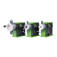
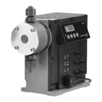
1.3.1 Pump types
The DDI 222 dosing pump is available for a variety of
performance ranges in various sizes:
The following is indicated on the pump nameplate
(see section 4.1 Identification):
• The pump type which specifies the stroke volume, connection
size and performance data (see below).
• The pump serial number which is used to identify the pump.
• The most important characteristics of the pump configuration,
e.g. dosing head and valve materials. They are described in
section 4.2 Type key.
• Maximum flow rate and maximum counter-pressure.
• Supply voltage or mains voltage and mains frequency.
1.3.2 Connection size
1. General information
4
1.1 Introduction
4
1.2 Service documentation
4
1.3 Information about the product
4
1.4 Applications
6
2. Safety
7
2.1 Identification of safety instructions in this manual
7
2.2 Qualification and training of personnel
7
2.3 Risks when safety instructions are not observed
7
2.4 Safety-conscious working
7
2.5 Safety instructions for the operator/user
7
2.6 Safety instructions for maintenance, inspection and
installation work
7
2.7 Unauthorised modification and manufacture of spare
parts
7
2.8 Improper operating methods
7
2.9 Safety of the system in the event of a failure in the
dosing system
7
2.10 Dosing chemicals
8
2.11 Diaphragm breakage
8
3. Transport and intermediate storage
8
3.1 Transport
8
3.2 Delivery
8
3.3 Unpacking
8
3.4 Intermediate storage
8
3.5 Return
8
4. Technical data
9
4.1 Identification
9
4.2 Type key
10
4.3 General description
11
4.4 Safety functions
11
4.5 Dimensional sketches
12
4.6 Weight
13
4.7 Materials
13
4.8 Control unit
13
5. Installation
14
5.1 General information on installation
14
5.2 Installation location
14
5.3 Mounting
14
5.4 Installation examples
14
5.5 Tube / pipe lines
16
6. Electrical connections
17
6.1 Connecting the signal lines for DDI 222
17
6.2 Connecting the power supply cable
19
7. Start-up/shutdown
19
7.1 Initial start-up / subsequent start-up
19
7.2 Operating the pump
20
7.3 Shutdown
20
8. Operation
20
8.1 Control and display elements
20
8.2 Switching on/off
20
9. How to use the control unit
21
9.1 Menu levels
21
9.2 General functions of the control unit
21
9.3 Signal outputs
23
9.4 First function level
24
9.5 Second function level
25
9.6 Calibration
29
9.7 Service level
31
9.8 Resetting to default settings
34
9.9 Current signal control 0-20 mA / 4-20 mA
34
9.10 Flow Monitor
38
9.11 Batch menu / batch mode
43
9.12 Timer menu / timer mode
44
9.13 Creating a master/slave application
45
9.14 Hotkeys / info keys
46
9.15 Pump safety functions
47
10. Maintenance
48
10.1 General notes
48
10.2 Maintenance intervals
48
10.3 Cleaning suction and discharge valves
48
10.4 Resetting the diaphragm
49
10.5 Diaphragm breakage
49
10.6 Replacing the diaphragm
49
10.7 Repair
50
11. Fault finding chart
51
12. Disposal
51
Warning
Prior to installation, read these installation and
operating instructions. Installation and operation
must comply with local regulations and accepted
codes of good practice.
These complete installation and operating
instructions are also available on www.grundfos.com.
Pump types
DDI 60-10
DDI 150-4
The pump for viscous liquids is called HV variant in
the following.
Pump type Connection size HV variant
DDI 60-10 DN 8 DN 20
DDI 150-4 DN 20 DN 20
 Loading...