English (GB)
14
5. Installation
5.1 General information on installation
5.2 Installation location
5.2.1 Space required for operation and maintenance
The control elements must be easily accessible during operation.
Maintenance work on the dosing head and the valves must be
carried out regularly.
Provide sufficient space for removing the dosing head and the valves.
5.2.2 Permissible ambient influences
Permissible ambient temperature: 0 °C to +40 °C.
Permissible air humidity: max. relative humidity:
92 % (non-condensing).
5.2.3 Mounting surface
The pump must be mounted on a flat surface.
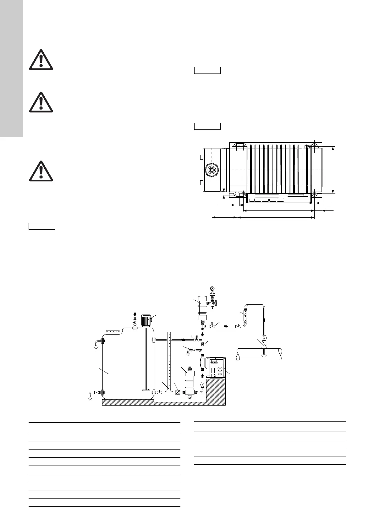
5.3 Mounting
Fig. 5 Drilling scheme
• Use four M6 screws to mount the pump on the tank or on a
console so that the suction valve is at the bottom and the
discharge valve is at the top (dosing always flows upwards).
5.4 Installation examples
Fig. 6 Installation example of pump with manual deaeration
Warning
Observe the specifications for the range of
applications and installation location described in
sections 1. General information and 5.2 Installation
location.
Warning
Faults, incorrect operation or faults on the pump or
system can, for example, lead to excessive or
insufficient dosing, or the permissible pressure may be
exceeded. Consequential faults or damage must be
evaluated by the operator and appropriate precautions
must be taken to avoid them!
Warning
Danger to life due to non-tripping of the residual
current device (RCD)!
If the pump is connected to an electric installation
where a residual current device (RCD) is used as an
additional protection, this RCD must trip when earth
fault currents with DC content (pulsating DC) and
smooth DC earth fault currents occur. This means
that a RCD type B, sensitive to universal current,
must be used.
The pump must be installed in a position where it is
easily accessible during operation and maintenance
work.
The installation site must be under cover!
Ensure that the enclosure class of motor and pump is
not affected by the atmospheric conditions.
Pumps with electronics are only suitable for indoor
use! Do not install outdoors!
Carefully tighten the screws, otherwise the plastic
housing may be damaged.
TM03 6664 4506
7
9.95
7
(159)
172.5
16.5
105
C1
TM03 6665 4506
1i
2i
3i
4i
5i
6i
7i
9i
10i
8i
15i
11i
12i
Pos. Components
1i Dosing tank
2i Electric agitator
3i Extraction device
4i Suction pulsation damper
5i Dosing pump
6i Relief valve
7i Pressure-loading valve
8i Pulsation damper
9i Calibration tube
10i Injection unit
11i Deaeration and evacuation valve
12i Check-back valve
15i Filter
Pos. Components
 Loading...