Option Installation
Chapter 2
2-8
3. Find the side of the option mounting bracket that is labeled with OPT. You will find this label in two spots
on this side.
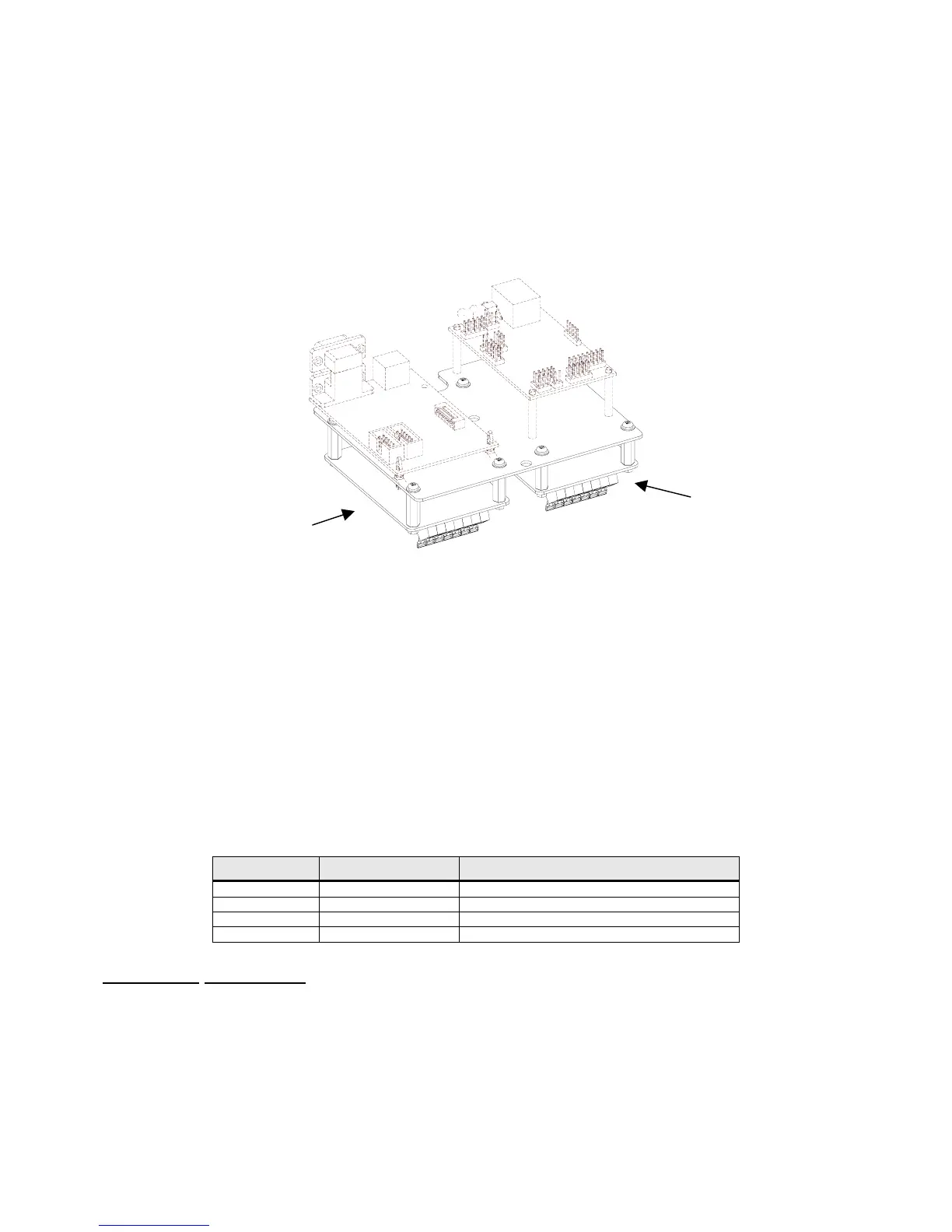
4. Line up the holes of the multi-scale option module with the holes located on the right side of the notch on
the option-mounting bracket.
5. Install the (4) aluminum standoffs in the holes with the (4) screws on the underside of the bracket
(labeled ETH). Refer to Figure 2-4 for configuration.
6. Position the multi-scale option module on the standoffs so the ribbon cable points away from the notch
on the option-mounting bracket. Install the (4) hex nuts to secure the option board.
Figure 2-4: Remote Scale Installation
7. Connect the 10" option ribbon cable 22-30-35454 (optional) from J1 of the multi-scale option module to
J1 of the main board.
8. Connect the load cell to J3 of the multi-scale option board.
9. Install the option-mounting bracket in the Model 675 enclosure. Refer to page 2-6 for option mounting
bracket installation instructions.
10. Reinstall the enclosure bottom plate.
F
OURTH
S
CALE
Provides a fourth scale input to be used with a remote scale. Use either the AUX 2 or AUX 3 ports on the
back panel for load cell connection. Use a 26-20-1870 strain relief.
Quantity Part Number Description
1 420919-36553 Multi-scale option board
4 17-20-3019 Aluminum standoffs
4 38-21-1640 Hex nuts
4 38-21-0101 Screws
Installation Instructions
1. DISCONNECT POWER! UNPLUG THE MODEL 675 TO INSURE DAMAGE WILL NOT OCCUR
DURING OPTION INSTALLATION.
2. Remove the (6) 38-31-8710 M5 x 0.8 x 10 mm screws from the enclosure bottom plate and set it aside.
3. Find the side of the option mounting bracket that is labeled with OPT. You will find this label in two spots
on this side.
Remote Scale
Remote Scale
 Loading...