Model 672/675 Technical Reference Manual
2-17
20 MA CURRENT LOOP CONNECTIONS
Apply the label to the outside of the Model 675 enclosure.
Transmit Current Input Active = TA
Transmit Current Input Passive = TP
Transmit Output = TXO
Receive Current Input = RXI
Receive Current Output = RX
The signal is bi-directional. Both the transmit output and the receive input of the indicator are available as 20
mA signals. The handshaking signals are not supported by the 20 mA current loop. Only baud rates of 9600
or less are supported.
The TXO output may be used as an active or passive output from the Model 675. Either active or passive is
chosen depending upon which terminals are used for the connections.
In active mode the indicator supplies the current. In passive mode, the external device supplies the current.
The RX input is available in passive mode only.
The input and output are electrically isolated from the main boards, earth ground and each other. This
applies for both passive and active modes. Isolation is a minimum of 1000 volts.
The active mode transmit current loop provides a driving voltage of 12 VDC. This will allow 20 mA current
flow with up to a 600 ohm load. Passive mode will work with an external driving voltage of up to 50 VDC.
D
D
A
A
T
T
A
A
B
B
A
A
S
S
E
E
O
O
P
P
T
T
I
I
O
O
N
N
The database option offers more memory storage for creating reports and tracking inventory.
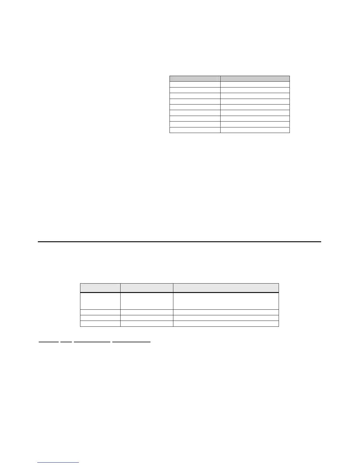
Table 2-6: Database Option Parts List
Quantity Part Number Description
1
420916-36371
420916-36372
420916-36373
256 K
1 Meg
2 Meg
3 17-20-3001 Aluminum standoffs
3 38-21-1640 M3 x 5.5mm hex nuts
3 38-21-0101 M3 x 0.5 x 6mm screws
Model 672 Installation Instructions
1. DISCONNECT POWER! UNPLUG THE MODEL 675 TO INSURE DAMAGE WILL NOT OCCUR
DURING OPTION INSTALLATION.
2. Remove the six 8 mm screws (size) from the bottom plate. Separate the top enclosure from the bottom
plate.
3. Locate the three small standoffs and remove the nuts.
4. Remove the Database option board from the anti-static bag.
5. Install the database over the three standoffs and snap the connector on the back of the board into J12 of
the main board.
6. Install the three nuts that were set aside in step 4 using a 5.5 mm nut driver. Be sure to tighten the board
snuggly. Do not over tighten.
Comm port 1 pin out Connection
1 No connection
2 RX IN
3 RX Pass
4 VCC
5 TX Active
6 Ground
7 TX OUT
8 TX Pass
9 Remote key
 Loading...