Option Installation
Chapter 2
2-18
7. Reinstall the top enclosure to the bottom plate.
8. Discard any leftover hardware.
Figure 2-11: Model 672 Database Option Installation
Model 675 Installation Instructions
1. DISCONNECT POWER! UNPLUG THE MODEL 675 TO INSURE DAMAGE WILL NOT OCCUR
DURING OPTION INSTALLATION.
2. Remove the (6) 38-31-8710 M5 x 0.8 x 10 mm screws from the enclosure bottom plate and set it aside.
3. Locate the J9 database header on the main board. There are three holes for the database mounting
hardware within the silk-screened rectangle on the main board.
4. Insert a M3 x 0.5 x 6mm screw through one of the mounting holes of the main board with the screw
head on the underneath side of the main board and hold it in place with your finger.
5. Install a 17-20-3001aluminum standoff by hand until it is finger tight on the M3 x 0.5 x 6mm screw and
tighten with a 6 mm nut driver.
6. Repeat steps 3 and 4 for the remaining screws and standoffs.
7. Place the database option board on the aluminum standoffs and secure with (3) 5.5 mm hex nuts.
8. Reinstall the enclosure bottom plate.
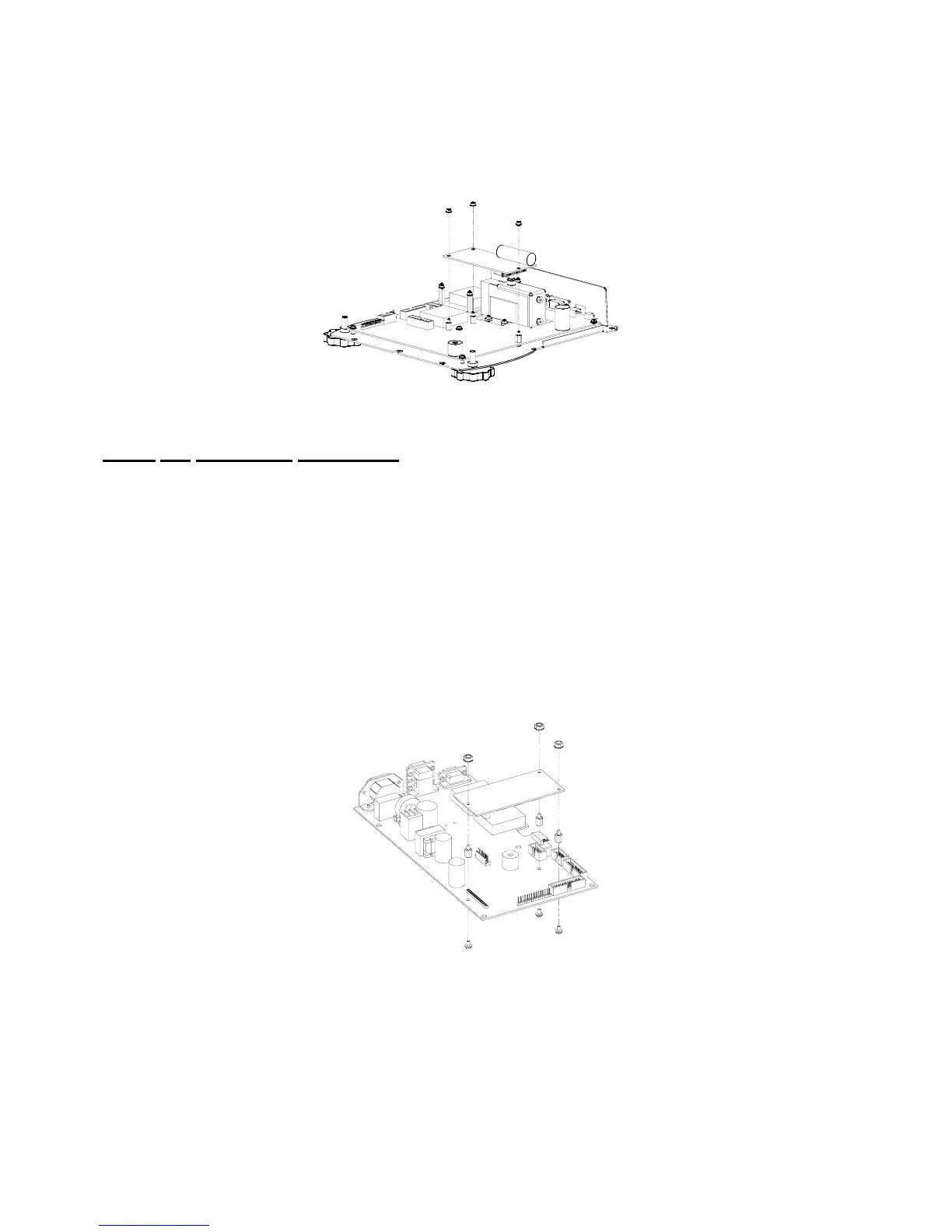
Figure 2-12: Model 675 Database Option Installation
 Loading...