Option Installation
Chapter 2
2-14
R
R
S
S
-
-
4
4
8
8
5
5
N
N
E
E
T
T
W
W
O
O
R
R
K
K
I
I
N
N
G
G
(
(
6
6
7
7
5
5
O
O
N
N
L
L
Y
Y
)
)
This section describes the installation of the RS-485 module. Installing this module will convert comm port 1
from RS-232 to RS-485. Refer to page 3-45 for more details on the RS-485 parameters and where to set the
network address.
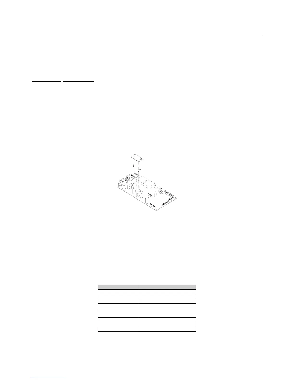
Installation instructions
1. DISCONNECT POWER! UNPLUG THE MODEL 675 TO INSURE DAMAGE WILL NOT OCCUR
DURING OPTION INSTALLATION.
2. Remove the (6) 38-31-8710 M5 x 0.8 x 10 mm screws from the enclosure bottom plate and set it aside.
3. Remove the U43 IC on the main board from its socket.
4. Remove the white wire jumper from the IC socket where the chip in step 2 was removed.
5. Snap the plastic spacers into the three mounting holes surrounding the U43 socket on the main board.
6. Gently press the option board into the socket.
7. Reinstall the enclosure back plate.
8. Connect wiring to the Comm 1 DB9 connector. Refer to Table 2-5 for more details.
Figure 2-9:
Installing the RS-485 Option
The RS-485 module does not have to be enabled in the setup mode. The module simply converts the
standard RS-232 communication on com port 1 to RS-485. However the advantage of using the RS-485
module, aside from the ability to transmit over long distances, is the ability to network multiple indicators or
parts counters using the same communication wires. When networking indicators, it is necessary to set up
a network address for each indicator. The network module itself does not require addressing, rather each
indicator must be enabled for network addressing in the setup mode. The RS-485 parameter (P250) must
be enabled and the network address (P251) must be set.
Table 2-5: RS-485 Comm Port 1 Connections
Comm port 1 pin out Connection
1 No connection
2 TX (B+)
3 TX (A-)
4 VCC
5 ISO ground
6 Ground
7 RX (A-)
8 RX (B+)
9 Remote key
 Loading...