Installation Manual
H3C S3600 Series Ethernet Switches Chapter 3 Installation
3-11
Step 3: Check that the PWR LED on the front panel of the switch is ON.
Caution:
Before powering on the switch, connect the ground wire.
3.2.2 Connecting the DC-Input Power Cord
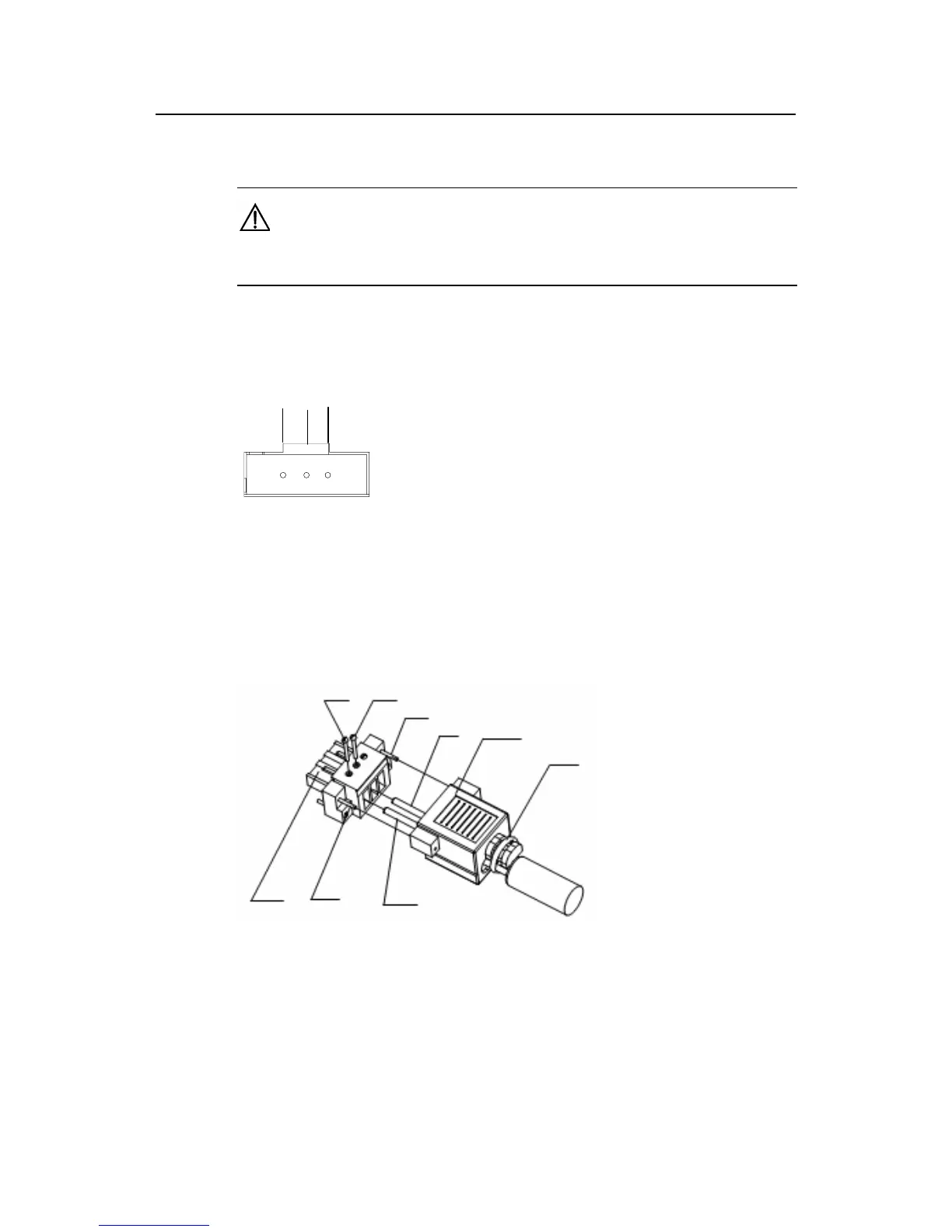
+-NULL+-NULL
+: –48V working ground -: –48 Vto –60 V
NULL: reserved
Figure 3-15 DC power connector (partial)
Step 1: Connect one end of the chassis ground wire to the grounding screw on the rear
of the chassis and the other end to the ground as near as possible.
Step 2: Connect DC socket.
Screw 1
Screw 2
Screw 3
Cable 1
Dust-proof shield
Cable tie
Connector
Screw 4
Cable 2
Screw 1
Screw 2
Screw 3
Cable 1
Dust-proof shield
Cable tie
Connector
Screw 4
Cable 2
Figure 3-16 RPS DC connector
1) As shown in
Figure 3-16, first insert two cables into the appropriate holes through
dust-proof shield, and then fix the cables separately by using screws 1 and 2.
Make sure that the positive and negative ends of the cable are inserted
appropriately and accord with silkscreen on the holes.

 Loading...


