P/N 53063-30, Manual revision: B
2-3
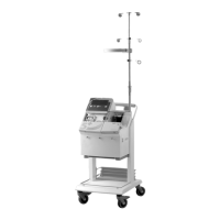
Describing the Cell Saver 5+ System Components
PRESENTING THE CELL SAVER 5+ SYSTEM COMPONENTS
This chapter identifies the major components of the Cell Saver 5+ system
and explains their intended utilization. Detailed installation and operating
instructions for the various protocols performed by the CS5+ device will be
provided in subsequent chapters.
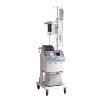
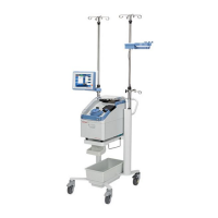
The CS5+ system consists of two groups of components: the device compo-
nents and the disposable set elements. The device controls the fluid pathway
provided by the disposable set. The device components include the control
panel elements and the hardware elements. A cart is provided with the
system for added maneuvrability and for adjusting the system to a proper
working height.
The controls and indicators for the CS5+ system have been streamlined
since earlier models, reflecting simplified operating procedures and
increased automation.
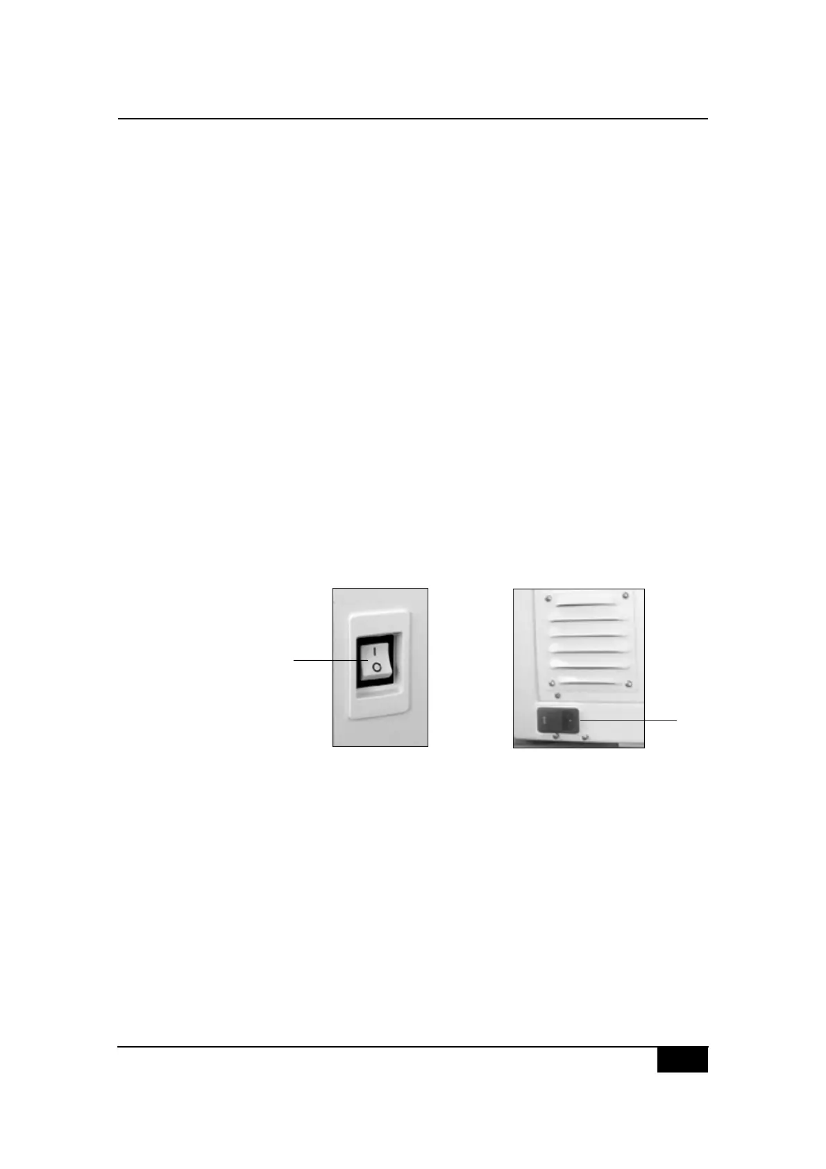
Power switch and power entry module
The ON/OFF power switch is located on the right side of the device.
The CS5+ device is a two-fuse system. The primary fuse is located in the
power entry module on the rear of the device. The secondary fuse is located
internally on the power supply and should only be replaced by trained
service personnel.
Figure 2-2, CS5+ power switch (A)
and power entry module (B)
A
B