117
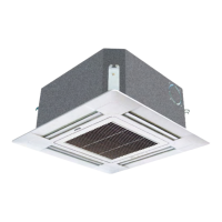
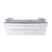
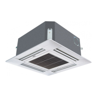
2-Way Cassette
Type Indoor Unit
The combination of multiple indoor units can be controlled by wired controller or remote controller.
※
Switching mode of Wired control master unit/ Wired control slave unit/ remote control types can be used for
switching over
※
Note:
The wiring for the power line of indoor unit, the wiring between indoor and outdoor units as well as the wiring
between indoor units:
Items
Total
current of
indoor units (A)
Cross
section
(mm
2
)
Length
(m)
Rated
current of
overow
breaker (A)
Rated current of residual circuit
breaker (A)
Ground fault Interrupter (mA)
Response time (S)
Cross sectional
area of signal Line
Outdoor
-indoor (mm
2
)
Indoor
-indoor (mm
2
)
<10 2 20 20 20 A, 30 mA, 0.1S or below
2 cores×(0.75-2.0)
mm
2
shielded line
≥10 and <15 3.5 25 30 30 A, 30 mA, 0.1S or below
≥15 and <22 5.5 30 40 40 A, 30 mA, 0.1S or below
≥22 and <27 10 40 50 50 A, 30 mA, 0.1S or below
※
The electrical power line and signal lines must be fastened tightly.
※
Every indoor unit must have the ground connection.
※
The power line should be enlarged if it exceeds the permissible length.
※
Shielded lays of all the indoor and outdoor units should be connected together, with the shielded
lay at the side of signal lines of outdoor units grounded at one point.
※
It is not permissible if the whole length of signal line exceeds 1000m.
Setting
mode
Socket/dip
switch
Wired control master unit Wired control slave unit Remote control
SW01-[2][3][4] All OFF [0][0][1] All OFF
CN21 socket Null Null Connect to remote receiver
Terminal block (control)
A,B,C connect with wired
controller
B,C connect with wired
controller
A,B,C null
Signal wiring of wired controller
Length of signal line (m) Wiring dimensions
≤ 250 0.75mm
2
×3 core shielded line
※
The shielding lay of the signal line must be grounded at one end.
※
The total length of the signal line shall not be more than 250m.