250
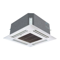
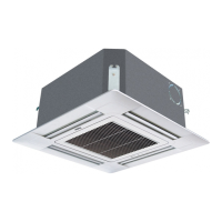
■ Concealed indoor units should be designed with air return plenum, as shown in Fig.2 & Fig.3.
■ The air blowing and return pipes should be equipped with an iron support xed on the roof precoated plate. The
joints at air pipes should be sealed with glue. It is recommended to keep the distance from the edge of air return
plenum to the wall to be over 150mm.
■ The gap between the air outlet port on the ue and the air outlet port on the air conditioner depends on the actual
installation sizes of ues and the operating static pressure terminals. The schematic diagram of the long and
short ues is shown in the following gure. When connecting the short ues, use the low static pressure terminal
in white and keep the distance between the air outlet port of the ue and the air outlet port of the air conditioner
to be less than 0.5m. When connecting the long ues, use the high static pressure terminal in red and keep the
distance between the air outlet port of the ue and the air outlet port of the air conditioner to be within 5m.
Installation of Duct Pipe of Indoor Units:
1. Installation of the air blowing pipe:
With a square blast pipe, the bore shouldn't be less than
the sizes of air outlet pipe.
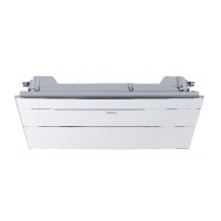
2. Installation of the air return pipe:
Connect one side of the air return pipes to the air return
port of the indoor units with rivets, with the other side
connected to air return shutter, as shown in Fig.1.
3. Heat Preservation of Blast Pipes:
Heat preservation lays should be provided for air
blowing & return pipes. Paste glue nails on the
blast pipes and attach thermo wool, which covered
by a layer of silver paper, x it with glue nail
cover, and then seal the joint with silver paper.
■ The drainpipe for condensed water should keep a gradient of 1%. The drain pipe should be insulated.
■ Hang the unit as shown in Fig.5.
Install the suspender:
■ Based on the normative installation for different building structure, install the machine with 4 M8 or M10
suspenders according to the outline drawing. When the height of the hoisting stud exceeds 0.9m, M10 studs
should be used. The level meter can be used for the horizontal installation.
■ Use the level meter to set the levelness of the machine to be within 5mm.
Ceiling
I
Air supply
Air outlet pipe
Air return
Air return plenum
Air outlet grid
Zoom in for A
Air
supple
No barrier within 1m
Machine
Air return
Air return plenum
Machine
M8 Wide expansion bolt
M8 Hanging stud
M8 Wide locking washer
M8 Nut
Unit
Sling dog
Drain pipe
Air return pipe
Air return shutter
Transient
air pipe
Air outlet port
Air outlet pipe
Air return shutter
Air return pipe
Indoor unit
Revit
Galvanizing plate
Thermo Wool
Glue nail cove
Rubber belt
Silver
paper
Glue nail
C