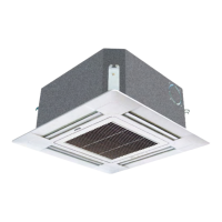
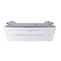
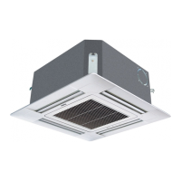
Medium ESP Duct Type
Indoor Unit (AD*MJERA)
313
Signal Wiring Drawing
Outdoor units are of parallel connection via three lines with polarity. The master unit, central control and all indoor
units are of parallel connection via two lines without polarity.
There are three connecting ways between wired controller and indoor units:
A. One wired controller controls multiple units, i.e. 2-16 indoor units, as shown in the above gure (1-5 indoor units).
The indoor unit 5 is the wired control master unit and others are the wired control slave units. The wired
controller and the master unit (directly connected to the indoor unit of wired control) are connected via three lines
with polarity. Other indoor units and the master unit are connected via two lines with polarity. SW01 on the wired
control master unit is set to 0 while SW01 on other wired control slave units are set to 1, 2, 3 and so on in turn.
(Please refer to the dip switch setting)
B. One wired controller controls one indoor unit, as shown in the above gure (indoor unit 6-19). The indoor unit
and the wired control are connected via three lines with polarity.
C. Two wired controllers control one indoor unit, as shown in the gure (indoor unit 20). Either of the wired controls
can be set to be the master wired controller while the other is set to be the slave wired controller. The master
wired controller and indoor units and the master and slave wired controller are connected via three lines with
polarity.
When the indoor units are controlled by the remote controller, refer to the "wired control master unit/ wired control
slave unit/ remote control unit table". A, B, C on signal terminal block needn't wires to connect with the wired
controller.