33
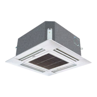
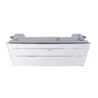
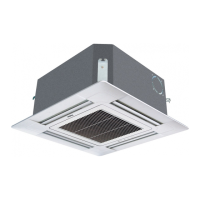
4-Way Cassette
Type Indoor Unit
The combination of multiple indoor units can be controlled by wired controller or remote controller.
※
Switching mode of wired control master unit/ wired control slave unit/ remote control types can be used for
switching over
※
Note:
The wiring for the power line of indoor unit, the wiring between indoor and outdoor units as well as the wiring
between indoor units:
Items
Total
current of
indoor units (A)
Cross
section
(mm²)
Length
(m)
Rated
current of
overow
breaker (A)
Rated current of residual circuit
breaker (A)
Ground fault interrupter (mA)
Response time (S)
Cross sectional
area of signal line
Outdoor
-indoor (mm²)
Indoor
-indoor (mm²)
<10 2 20 20 20 A, 30 mA, 0.1S or below
2 cores×(0.75-2.0)mm
2
shielded line
≥10 and <15 3.5 25 30 30 A, 30 mA, 0.1S or below
≥15 and <22 5.5 30 40 40 A, 30 mA, 0.1S or below
≥22 and <27 10 40 50 50 A, 30 mA, 0.1S or below
※
The electrical power line and signal lines must be fastened tightly.
※
Every indoor unit must have the ground connection.
※
The power line should be enlarged if it exceeds the permissible length.
※
Shielded lays of all the indoor and outdoor units should be connected together, with the shielded lay at the side of
signal lines of outdoor units grounded at one point.
※
It is not permissible if the whole length of signal line exceeds 1000m.
Signal wiring of wired controller
Length of signal line (m) Wiring dimensions
≤ 250 0.75mm
2
×3 core shielded line
※
The shielding lay of the signal line must be grounded at one end.
※
The total length of the signal line shall not be more than 250m.
Setting
mode
Socket/dip
switch
Wired control master unit Wired control slave unit Remote control
SW01-[1][2][3][4] All OFF [0][0][0][1] All OFF
CN21 socket Null Null
Connect to remote
receiver
Terminal block (control)
A, B, C connect with wired
controller
B, C connect with wired
controller
A, B, C Null