620
Dip switch instruction:
SW01 is used to set wire controlled address of and set capabilities of master; SW03 is used to set indoor unit
address (combine original communication address and address of centralized controller).
(A) Denition and description of SW01
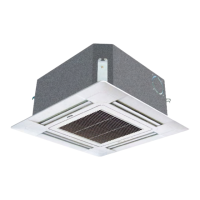
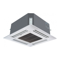
Note: A wired controller can connected to at most sixteen ultrathin indoor units.
SW01_1
SW01_2
SW01_3
SW01_4
Address of
wire controlled
indoor unit
(group
address)
[1] [2] [3] [4] Address of wire controlled indoor unit (group address)
OFF OFF OFF OFF 0#(wire controlled master unit)(default)
OFF OFF OFF
ON 1#(wire controlled slave unit)
OFF OFF
ON OFF 2#(wire controlled slave unit)
OFF OFF
ON ON 3#(wire controlled slave unit)
... ... ... ... ......
ON ON ON ON 15#(wire controlled slave unit)
SW01_5
SW01_6
SW01_7
SW01_8
Capability of
indoor unit
[5] [6] [7] [8] Capability of indoor unit
OFF OFF OFF OFF 0.6HP(AS052MN/FERA)
OFF OFF OFF
ON 0.8HP(AS072MN/FERA)
OFF OFF
ON OFF 1.0HP(AS092MN/FERA)
OFF OFF
ON ON 1.2HP(AS122MN/FERA)
OFF
ON OFF ON 1.7HP(AS162MN/FERA)
OFF
ON ON OFF 2.0HP(AS182MN/FERA)
OFF
ON ON ON 2.5HP(AS242MN/FERA)
ON OFF OFF OFF 3.0HP(AS282MNERA)
ON OFF OFF ON 3.2HP(AS302MNERA)
LED light introduction:
• LED1, LED2: communication lamp between indoor unit and wired controller.
These two lamps icker alternately under normal condition; once occurs the communication faulty, these
two lamps will light or not light at the same time.
• LED3, LED4: communication lamp between indoor unit and outdoor unit.
These two lamps icker alternately under normal condition; once occurs the communication faulty, these
two lamps will light or not light at the same time.
• LED5: malfunction lamp of indoor unit.
This lamp not light under normal condition; once indoor unit occurs malfunction this lamp will icker, icker
times indicate the corresponding failure code.
• LED6: power light