17
Subject to change without notice
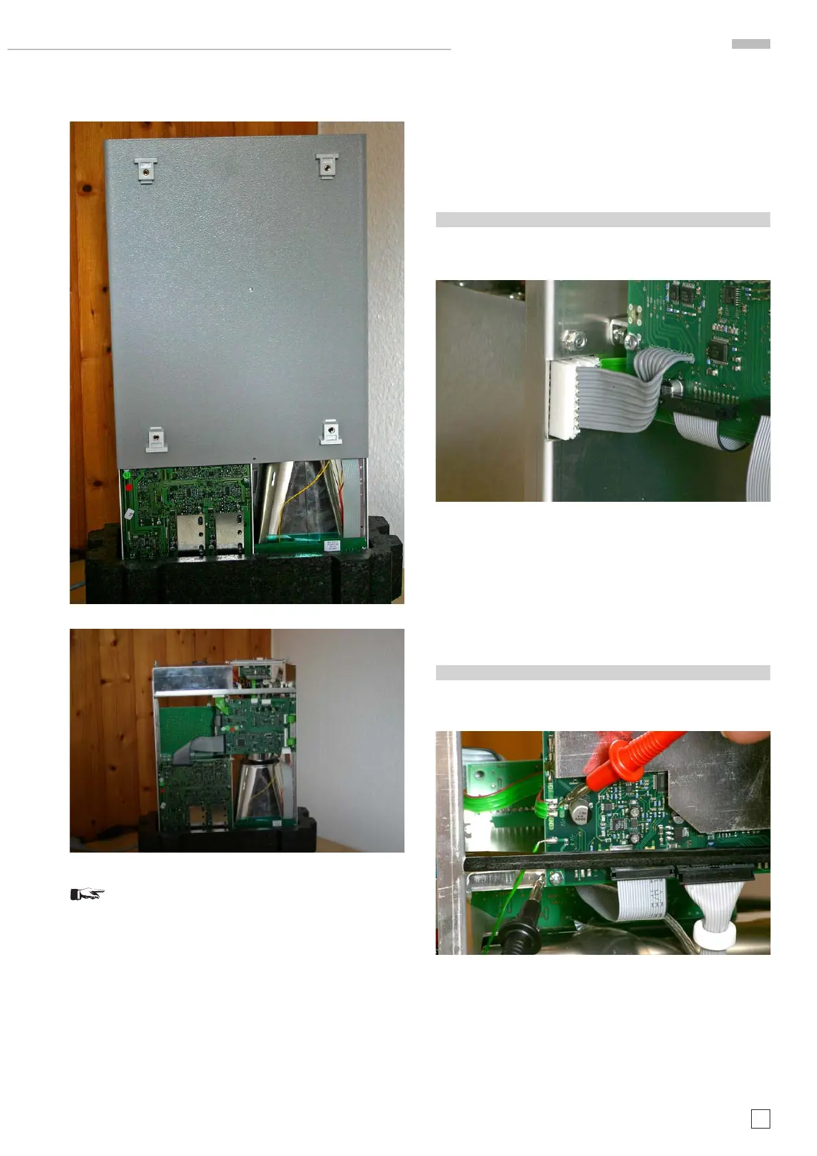
HM1508-2 Troubleshooting
3. Set the front face of the oscilloscope on a soft surface and
pull the cabinet off. (Photo A6 and A7)
Photo A6
Photo A7
Please note:
After repair work, close the instrument in reverse
order of above.
B: Preliminary Test!
The precondition for undistorted operation is correct supply
voltages generated by the power supply. It is highly recom-
mended to check the power supply output voltages before any
other action.
The following steps show you what to do.
1.1 Miscellaneous voltages
Locate and identify a Molex 8 pole connector J1002 (at the inner
side of the vertical rear chassis) where an 8 pole ribbon cable
coming from the MB board is connected. See photo B1.1.
Photo B1.1
All voltages are measured with respect to ground (chassis).
The following voltages must be present:
– Pin 1: approx. +115 V
– Pin 2: +65 V (± 0.5 V)
– Pin 4: approx. +5.2 V
– Pin 6: +12 V (± 50 mV)
– Pin 8: approx. -6 V
1.2 +5 V
Locate and identify Molex connector J1003 (3 pole ribbon cable)
connecting the power supply board with the MC board (marked
“+5V” on the pcb) on the MC board. See photo B1.2.
Photo B1.2
The voltage at “+5V” should be approx. + 5V.
1
8

 Loading...


