18
Subject to change without notice
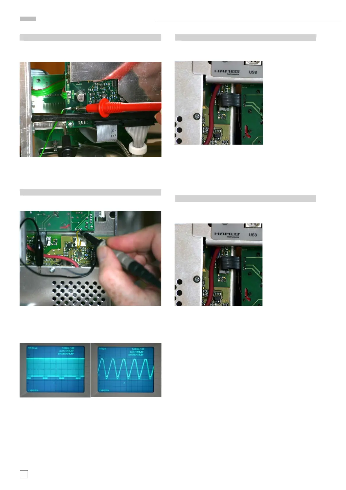
1.3 +5 V IF
Locate and identify J1005 (1 litz wire) connecting the power
supply board with the MC board (marked “+5 V IF” on the pcb)
on the MC board. See photo B1.3.
Photo B1.3
The voltage at “+5 V IF” should be approx. + 5V.
1.4 “Pump Voltage”
Locate and identify Molex connector J1008 pin 2 (1 wire) connec-
ting the power supply with the CR board. See photo B1.4.1.
Photo B1.4.1
Measure the “Pump Voltage” using an oscilloscope. See photo
B1.4.2 and B1.4.3
Photo B1.4.2 Photo B1.4.3
Note: The pump voltage indicates the switch mode power supply
switching frequency.
1.5 -2 kV
Locate and identify Molex connector J1009 (4 wires) connecting
the power supply board with the CR board. See photo B1.5.
Photo B1.5
Check that the probe and the measuring instrument are sui-
table for measuring voltages up to 2.5 kV.
Measure approx. -2 kV at pin 3.
1.6 Focus Voltage
Locate and identify Molex connector J1009 (4 wires) connecting
the power supply board with the CR board. See photo B1.6.
Photo B1.6
Check that the probe and the measuring instrument are sui-
table for measuring voltages up to 2.5 kV.
Measure approx. -1.5 kV at pin 4.
HM1508-2 Troubleshooting
1
1

 Loading...


