19
Subject to change without notice
1.7 +12 kV
1.7.1 +12 kV measurement
– Switch the instrument off!
– Locate and identify the high voltage connector at the front
of the crt cone.
– Be sure not to get in contact with metal parts of the high
voltage connector during the following procedure!
– Set a multimeter to DC measurement and select a suitable
range for high voltage measurement in combination with a
high voltage probe (specifi ed for 14 kV or more).
– Connect the reference potential connector of the high vol-
tage probe with chassis.
– Lift the rubber of the high voltage connector and move the
probe tip in the gap between crt glass and rubber to get in
contact with the high voltage connector.
– Switch the oscilloscope on.
The multimeter should display approx. 12 kV.
Note:
If no high voltage probe is available the measurement
can be made in one of the following ways.
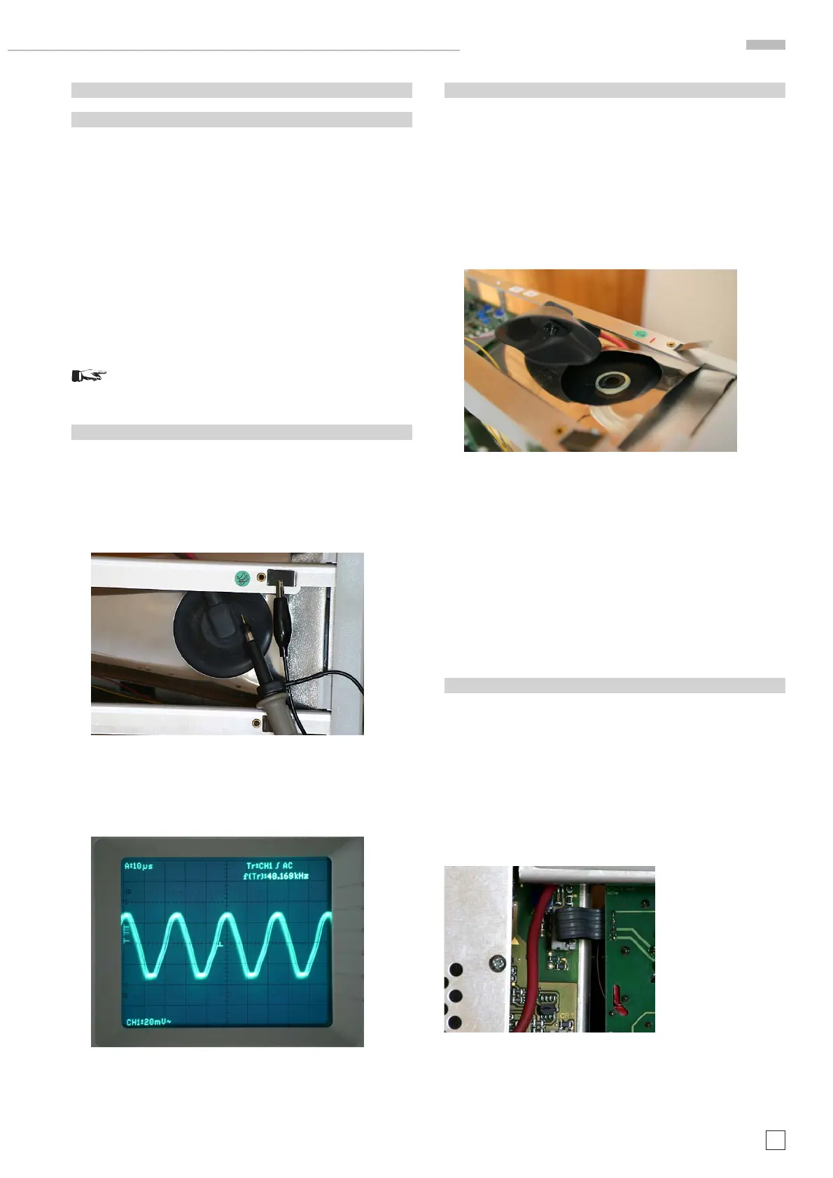
1.7.2
– Locate and identify the high voltage connector at the crt
cone.
– Indicate the presence of the high voltage by aid of an oscil-
loscope.
– Position the tip of a *10 probe (10:1 divider probe) in approx.
5 mm distance of the high voltage connector clip. See photo
B1.7.1.
Photo B1.7.1)
A sine wave signal indicating the high voltage generator
frequency (approx. 40 kHz) and the AC ripple on the high
voltage should be visible. See photo B1.7.2.
Photo B1.7.2
This indicates that the high voltage multiplier is working pro-
perly.
1.7.3
Please note that the crt and the voltage multiplier can still be
charged although the instrument is switched off.
– To discharge connect a cable at one side with chassis and
solder a 50 kOhm resistor on the other side. Use an isolated
tool to move the resistor to the crt high voltage connector
and thereafter to the high voltage connector clip to dischar-
ge both via the resistor.
– Switch the instrument off!
– Remove the high voltage connector (clip) at the crt cone and
put it in position where the distance to the chassis or crt
mu-metal screening is approx. 20 mm. See photo B1.7.3.
Photo B1.7.3
– Make all safety precautions to be sure that nobody can get
in contact with the high voltage clip!!!
– Switch the oscilloscope on.
If a fi zzing noise can be heard, the high voltage is pre-
sent.
– Switch the instrument off!
– Insert the high voltage connector into the hole in the crt
shielding, press the crt clip rubber so that the clip can be
inserted into the high voltage connector hole in the crt.
– Check that the high voltage clip is securely fi xed.
1.8 CRT Heater
Look between the CRT mu-metal shielding and the CR board
to see whether the heater (fi lament) glows.
Attention: The heater voltage is superimposed on -2 kV.
Note:
If all measurements and tests have been completed success-
fully except this item, switch the oscilloscope off.
Locate and identify Molex connector J1009 (4 wires) connecting
the power supply board with the CR board. See photo B6.
Photo B1.8
Disconnect the ribbon cable from J1009.
Use an Ohm meter to measure approx. 15 Ohm between wire
1 and 2 leading to pin 1 and 14 (heater) of the CRT.
1
HM1508-2 Troubleshooting

 Loading...


