20
Subject to change without notice
If the heater seems to be defective, remove the CRT socket and
measure the CRT heater resistance between pin 1 and 14 to
eliminate the CRT socket.
1.9 Measures
If one of these voltages is missing or strongly deviating the
following procedure is recommended:
– Disconnect the instrument from mains/line.
– Remove the interface mounting plate.
– Remove the power supply shielding.
– Unsolder the wire soldered to the protective earth (PE)
connection at the inner side of the rear chassis, marked
by an earth symbol.
– Remove all cables and wires connected to the power sup-
ply.
– Unfasten the power supply mounting nuts.
– Remove the power supply and replace it by a new power
supply.
Proceed in reverse order to mount the new power supply.
Attention!
Special care must be taken for the protective earth connection
(PE). It must be fi xed and thereafter soldered in such a way
that even accidental contact with a soldering iron doesn`t
open the connection.
Security check!
Check that after PS board replacement the protective earth
connection is reestablished.
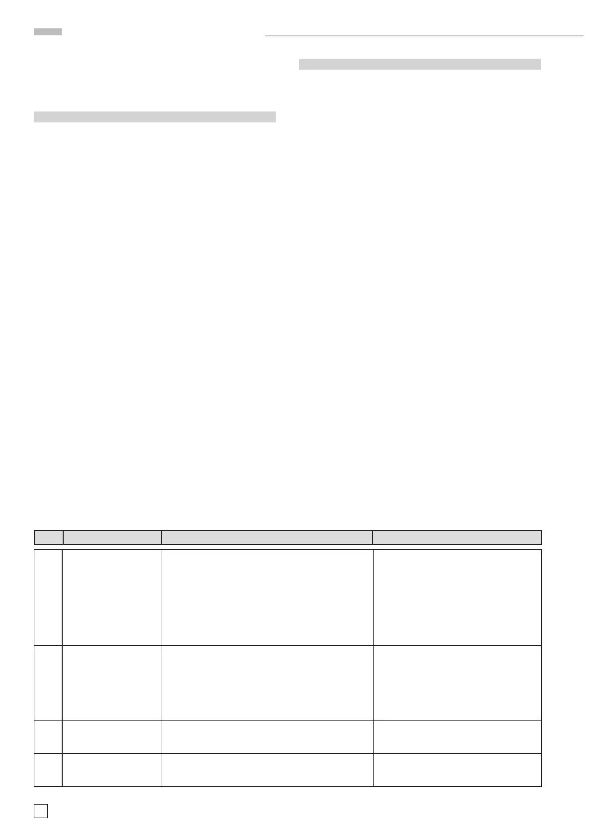
Item Instrument Behavior What to do Remark
2.1 No front panel LED lit,
no trace and no readout
visible on the screen.
Pull out fuse holder and check the (external accessible)
fuse. If the fuse is blown, replace it and switch the ins-
trument on again.
If the error is still present, and the (external accessible)
fuse is blown again, continue with item 2.3.
If the (external accessible) fuse is not blown, continue
with item 2.2.
The instrument must be disconnected from
mains/line before checking the fuse.
2.2 Remove the power supply shielding as described under
item 1.9 and check the (internal accessible) fuse on the
PS board. If the fuse is blown, replace it and switch the
instrument on again.
If the error is still present, and the (internal accessible)
fuse is blown again, continue with item 2.3.
The instrument must be disconnected from
mains/line before checking the fuse.
2.3 Replace the power supply by a new one as described
under item B1.9 and adjust the new power supply (item
1.10).
2.4 Security check!
Check that after PS board replacement the protective
earth connection is re established.
1.10 Adjustment after power supply change.
The following procedures are required after changing a power
supply due to tolerances.
– Check and adjust +65 V and +12V as described under item
1 and 2 in the Adjustment Procedure.
– Press SETTINGS pushbutton, select “Self Cal” and “Start”
the self calibration.
– Check time base and Y accuracy and make corrections if
required (Adjustment Procedure item 25, 59 and 60).
C: Error Diagnostics
The following examples will help you to determine the board to
be replaced or repaired. Due to each board’s comprehensive
functions it is not always possible to determine one board
precisely. Thus it might be necessary to change more than
one board.
As explained before under item B 1, the power supply check
has the highest priority.
The MC board has the second highest priority, as it controls
most of the other boards with the exception of the power supply
board. Thus if the power supply is ok, but no trace becomes
visible and/or the instrument does not respond to the controls
it is recommended to change the MC board fi rst.
If the MC board was the reason for an error and is replaced,
don`t forget to make a new adjustment of item 62 as described
in the Adjustment Procedure.
Attention!
It is recommended to reinstall the old board if a new board
did not solve the problem.
HM1508-2 Troubleshooting

 Loading...


