21
Subject to change without notice
Item Instrument Behavior What to do Remark
3.1 Analog and digital mode:
No trace and no readout
visible on the screen. Ana-
log/Digital LED lit.
Select analog mode.
Press AUTOSET pushbutton to make the trace visible.
This description assumes that the crt heater
glows as described under item 1.8.
3.2 Switch the oscilloscope off before continuing with item
3.3!
3.3 Remove the plastic cap and make a short between pin 2
(cathode) and pin 3 (grid 1).
See photo C3.3.
3.4 Switch the oscilloscope on and watch if the trace becomes
visible with a too high intensity.
If yes continue with item 3.5.
If not continue with item 3.8.
No potential difference between cathode
and grid 1 causes maximum beam current
in the crt and should only be permitted for
a few seconds.
3.5 Locate and identify pin 2 at Molex connector J5003 on MB
board and continue with item 3.6.
See photo C3.5.
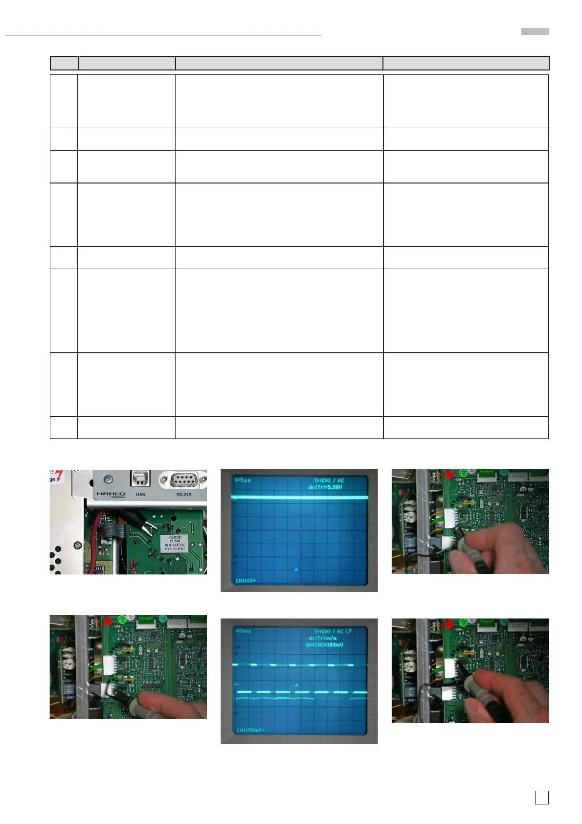
3.6 Measure the “BLANK” signal using an oscilloscope with
a *10 probe.
If the signal is present exchange the CR board and con-
tinue with item 3.7.
If the signal is not present continue with item 3.11 (re-
placement of MB board).
See photos C3.6.1 (DC coupling) and C3.6.2
(AC coupling)
3.7 If trace and readout are visible thereafter, a readjustment
of item 5 (CRT minimum intensity), 6 (Focus symmetry)
and 7 (Astigmatism correction) is required.
Thereafter the time base and Y accuracy must be checked
and if necessary corrected (item 24, 25, 59 and 60).
The adjustments are described in the Adjust-
ment Procedure.
3.8 Locate and identify pin 1 and 6 at Molex connector J4800
on MB board and continue with item 3.9.
See photos C3.8.1 and C3.8.2
photo C3.3
photo C3.5
photo C3.6.1
photo C3.6.2
photo C3.8.1
photo C3.8.2
HM1508-2 Troubleshooting

 Loading...


