22
Subject to change without notice
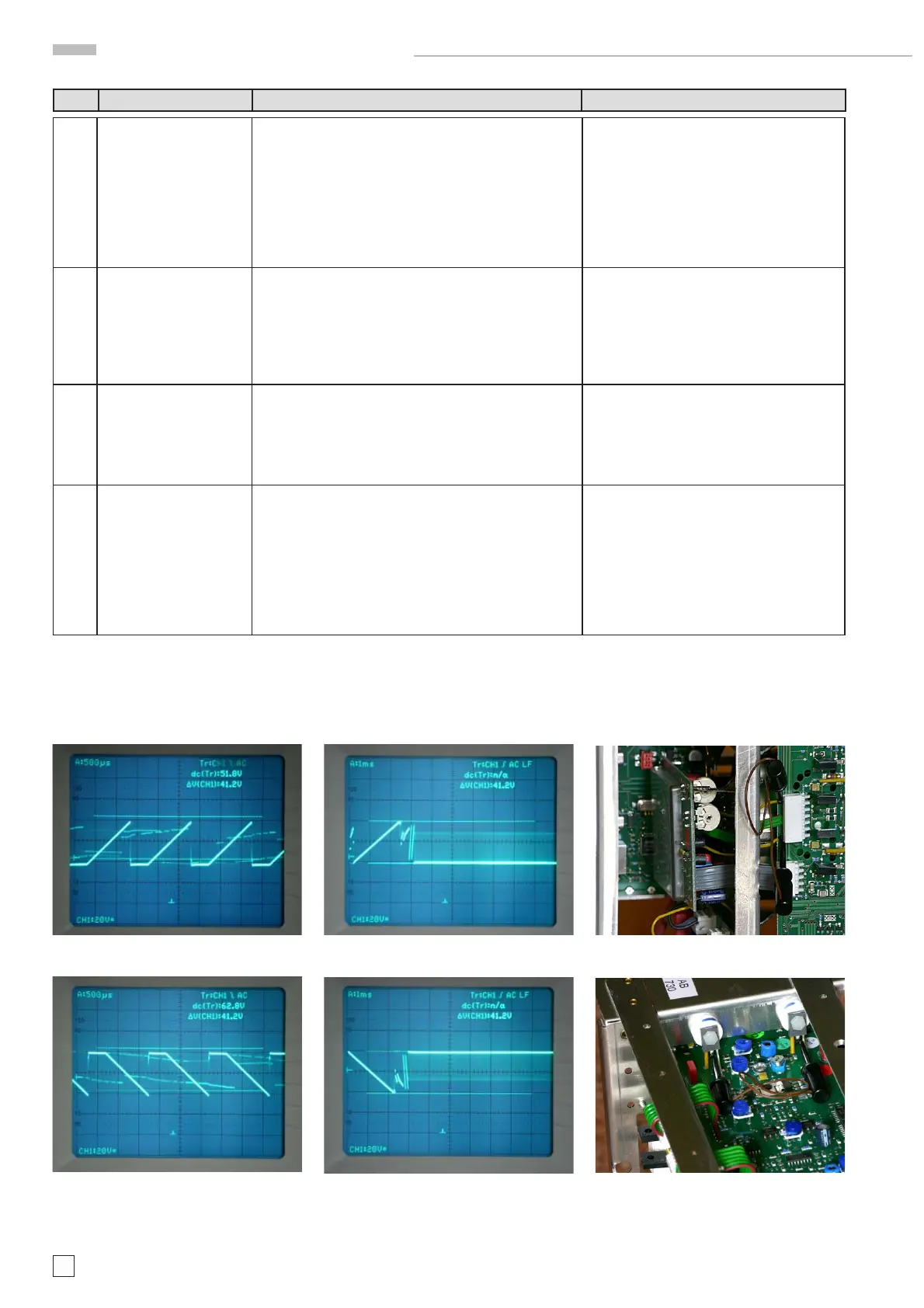
3.9 Measure the sawtooth signal using an oscilloscope with
a *10 probe or alternatively the method described under
item 3.10.
If the signals are not present the X defl ection (MB board)
is the reason for the error and the MB board must be
changed. Continue with item 3.11.
Otherwise continue with item 3.12
See photos C3.9.1 and C3.9.2 made in analog
mode.
See photos C3.9.3 and C3.9.4 made in digital
mode.
3.10 Connect pin 1 and 6 at J4800 on MB board by a short.
Now a bright spot should become visible in the screen
center.
If this is case the MB board must be changed. Continue
with item 3.11.
See photo C3.10
If due to the short both X defl ection plates
have the same potential, the beam is unde-
fl ected and should be in the screen center.
3.11 Replace the MB board to see if trace and readout are
present.
If this is the case the following adjustments must be made
as described in the Adjustment Procedure: 24, 37 – 45,
57 – 61 and 63 - 64.
3.12 Locate and identify the Y fi nal stage transistors mounted
at the rear chassis.
Connect the both collectors by a wire (short). The collec-
tors are the center leads of the transistors.
If the trace becomes visible continue with item 3.13.
If the trace does not become visible continue with item
3.15.
See photo C3.12
Item Instrument Behavior What to do Remark
photo C3.9.1
photo C3.9.2
photo C3.9.3 photo C3.10
photo C3.12
photo C3.9.4
HM1508-2 Troubleshooting

 Loading...


