36
Subject to change without notice
– The maximum acceptable deviation at the 10
th
or 11
th
pulse
or zero crossing is ±3 mm (3%).
Performance Check:
– Set TIME/DIV knob for “TB: 50ns” display.
– Connect a 50ns time mark signal or a 20 MHz sine wave
signal (accuracy 0.1 ppm or better) to the input of CH 1.
– Turn CH 1 VOLTS/DIV knob for a signal height of approxi-
mately 5 divisions.
– Set LEVEL A/B knob on the front panel for stable trigge-
ring.
– Check the accuracy at this setting.
– Turn TIME/DIV knob one step counter clockwise and note
the time base and signal frequency information displayed
by the readout.
– Repeat this procedure until the 20 ms time base setting has
been checked.
– Press Menu Off key until a menu is no longer displayed and
COMP. TESTER mode is present.
– Continue with item 34.
34. Time Base A: Magnifi cation x10 (Analog)
– Set TIME/DIV knob for “TB: 50μs” display.
– Press MAG x10 pushbutton so that it light.
– Check that the readout displays A:5μs.
– Connect a 5μs spike pulse or 200 kHz sine wave signal
(accuracy 0.1 ppm or better) to the input of CH 1.
– Turn CH 1 VOLTS/DIV knob and sine wave generator output
level for approx. 5 divisions signal height.
– Set LEVEL A/B knob on the front panel for stable trigge-
ring.
Accuracy reading:
– Set POSITION 1 knob on the front panel for reading of the
pulse peak or sine wave zero crossing at the horizontal
center line of the graticule.
– Move trace with HORIZONTAL knob (front panel) so that the
fi rst pulse peak or sine wave zero crossing coincides with
the fi rst or second vertical graticule line at the left side of
the screen.
– Check that 1 pulse or signal period per division is displayed
and the rightmost pulse peak or zero crossing coincides with
the vertical graticule line as on the left side = 0% error.
– The maximum acceptable deviation at the 10
th
or 11
th
pulse
or zero crossing is ±5 mm (5%).
– Press MAG x10 pushbutton to switch 10 fold magnifi cation
off.
– Check that the readout displays A:50μs.
– Continue with item 29.
35. Digital Time Base Accuracy
– Press ANALOG/DIGITAL key to switch over to digital mode.
– Connect a 50μs spike pulse or 20 kHz sine wave signal
(accuracy 0.1 ppm or better) to the input of CH 1.
– Turn CH 1 VOLTS/DIV knob and sine wave generator output
level for approx. 5 divisions signal height.
– Set LEVEL A/B knob on the front panel for stable trigge-
ring.
Accuracy reading:
The accuracy reading should always be performed in the
following way:
– Set POSITION 1 knob on the front panel for reading of the
pulse peak or sine wave zero crossing at the horizontal
center line of the graticule.
– Move trace with HORIZONTAL knob (front panel) so that the
fi rst pulse peak or sine wave zero crossing coincides with
the fi rst or second vertical graticule line at the left side of
the screen.
– Check that 1 pulse or signal period per division is displayed
and the rightmost pulse peak or zero crossing coincides with
the vertical graticule line as on the left side = 0% error.
– The maximum acceptable deviation at the 10
th
or 11
th
pulse
or zero crossing is ±3 mm (3%).
– Press ANALOG/DIGITAL key to return to analog mode.
36. Z Input
– Check that ANALOG MODE is present.
– Check that “External” triggering is not active.
– Press CH 3/4 pushbutton to call the “Z Input” menu (im-
possible when “External” trigger mode is chosen).
– Press “On” function key to activate the Z Input function.
– Set time base to 20 μs/div.
– Connect a 2.5 Vpp, 1 Hz square wave signal (switching
between 0 V and 2.5 V and vice versa) to input CH 4.
– Check that the trace is continuously switching between
unblank and blank.
37. COMP. Tester Function
– Press button below the CRT to open the “Utilities” menu.
– Press “Comp. Tester” function key to switch over to “On”.
– Check that a horizontal trace of approximately 9 div. length
is displayed.
– Connect both “COMP. TESTER” sockets by a short piece of
wire.
– Check that the trace is displayed in vertical direction with
approximately 8 div. height.
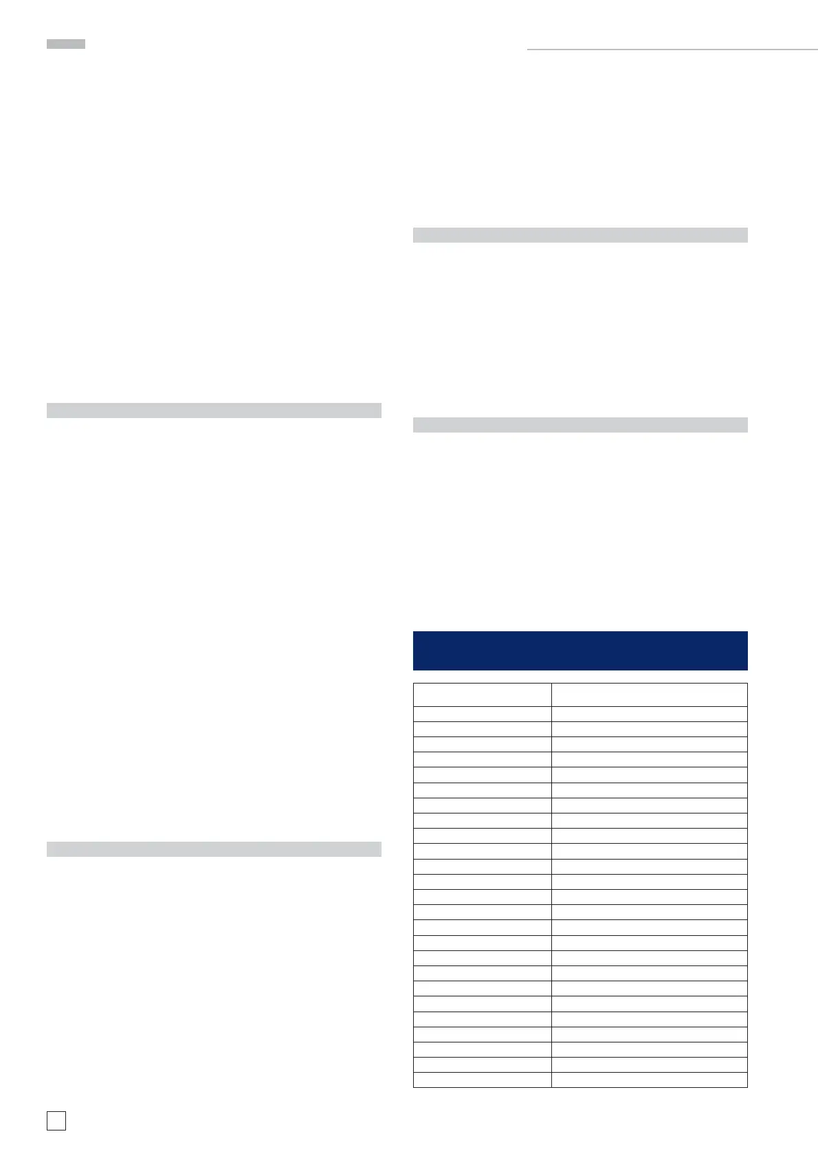
Adjustment and Performance Check HM1508-2
Spare Part Spare Part Number
AB Board 29-1000-0033
CRT Board, CR151 29-1000-0021
CRT Modul (Tube) 29-1000-0024
FC Board 29-1000-0061
IF Board 29-1000-0069
MB Board, V1.0 29-1000-0019
MC Board 29-1000-0062
PS Board, V1.0 29-1000-0015
TE Board 29-1000-0060
USB Board 29-1000-0063
YF Board, F151 29-1000-0032
YP Board 29-1000-0052
Front Cover 29-1000-0066
Rear Cover 29-1000-0025
Casing 29-1000-0064
Handle 29-1000-0068
Knob Set 29-1000-0029
Screenfi lterpane 29-1000-0027
Cable Set 29-1000-0065
Keymat 29-1000-0067
PS Board, V2.0 29-1000-0119
YF Board, F152 29-1000-0122
MB Board, V1.1 29-1000-0123
CRT Board, CR152 29-1000-0120
Delay Line 29-1000-0023
Spare-Part List HM1508-2

 Loading...


