37
Subject to change without notice
The HZ620 Test Generator is designed for testing/adjusting
oscilloscopes. The following is a concise description of the
HZ620 including the accessories and the signals. Basic
knowledge of an oscilloscope’s architecture and adjustment
procedure is assumed.
HZ620 can be used as a ‘stand-alone’ instrument or in con-
junction with a relay-box for signal routing.
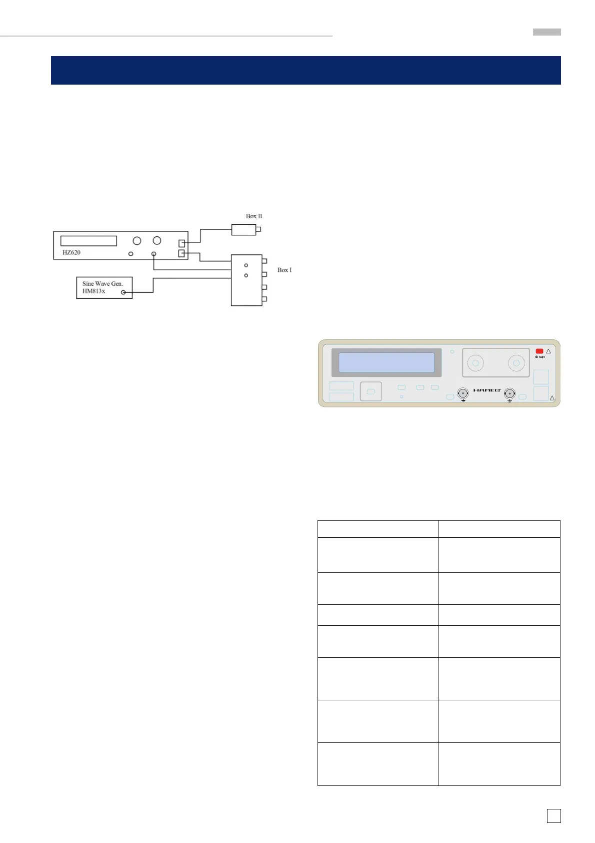
Scheme of HZ620, Boxes and Sine-wave generator
The boxes are connected to the front panel of HZ620 with RJ45
connectors (CAT5 STP cable) for control, Box I additionally with
BNC-SMA coaxial-cables to HZ620 and sine wave generator
HM813x. Inside Box I are 2:1 Attenuators, relays for signal
routing and 50 Ohm termination resistors.
Several types of Box I will be available for connecting to 2-Ch
or 4-Ch HAMEG-oscilloscopes. Box I is also named HM1x0xLF-
Box. Note that some functions of Box I are only accessible via
Interface commands.
Box II contains a square-wave generator with fast rising
edges.(also called HM1x0xHF-Box)
Signals of HZ620
It provides either a positive dc voltage or a square wave ranging
from 0.5Hz to 100kHz.(rise/fall time ~100ns) Output voltages
from +10mV to +40V (in 1/2.5/5 sequence, except 40V) with an
amplitude accuracy of 0.1% are available. In the 10mV to 50mV
range the source resistance is 50 Ohm, in the 0.1V to 40V range
the source resistance is 600 Ohms. This signal is used for ad-
justing the scope’s input capacitance, attenuator compensation
networks, other low frequency compensation elements or the
gain of the amplifi er chain.
A fast rising square wave is delivered by the external box (Box
II). The rise/fall time is about 0.8ns. The amplitude is approx.
+25mV/50 Ohm (not calibrated). The frequency is 0.5Hz to 2MHz
in 1-2-5 steps.
In order to ensure best waveform fi delity, the box should be
connected via a 50 Ohm termination resistor to the oscilloscope
input without a cable. The fast rising square wave is necessary
for adjusting the high frequency compensation networks of the
scope’s amplifi ers.
Time mark pulses for testing/adjusting the time-base. The fre-
quency of the time mark pulses ranges from 0.5Hz to 100MHz
which corresponds to 2s/div to 10ns/div of the oscilloscope’s
time-base. The amplitude is constant +0.25V peak at 50 Ohm.
The duty cycle is about 0.05, increasing to 0.5 in the 10MHz to
100Mhz range.
For testing the logic channels of HM2008, four LVDS-signals
are delivered at the 16-pin connector with frequencies from
200 kHz to 1 MHz or 20 MHz on all four channels. The logic
outputs should be connected via a fl at cable directly to the logic
inputs of the scope without a logic-probe.
For checking/adjusting the threshold of the logic inputs, a dc
voltage from –2V to +3V with 1mV resolution is provided by
HZ620. The max. current is 5mA. It is also useful for testing
the DC-gain linearity of the Y-amplifi er.
By means of an external video source (CVBS-Video signal),
connected at the rear side of HZ620, the scope’s Videotrigger
circuit can be tested in both polarities.
Operating the HZ620
The initial setting is always ‘Square wave, 5kHz, 25mV, Output
Off’.
HZ620 HINT 13.07.07 gw
HZ620 DKL 13.07.07 gw
POWER
!
MADE IN GERMANY
!
EXT.
FREQUENCY
< SIGNAL >
TEST GENERATOR
HZ620
LOGIC CHANNELS
SUB FUNCTION
CAL.
AUX
ON
FREQUENCY
AUX
OUTPUT
HZ620 TXT 13.07.07 gw
Instruments
AMPLITUDE
OUTPUT
ON
BOX
II
BOX
I
CONTRAST
Selecting Signals and Sub Functions
The ‘< SIGNAL >’-buttons selects the various signals succes-
sively in both directions.
The ‘Sub Function’ button activates an additional function,
depending on the selected signal.
The following table shows the sequence of the signals and the
related sub-function:
Signal Sub Function
-Sqr 0.5Hz-100kHz, 10mV-
40V
ATT 2:1 activates the 2:1 At-
tenuator in Box I
-Pulse, 0.5Hz-100MHz,
0.25V@50 Ohm
no sub function
-Logic-Probe Channels 20MHz at all four channels
-DC voltage –2V to +3V,
10mA
no sub function
-Ext. Video, fed through from
an external source to the out-
put connector of HZ620
Video invert
-HF-Box II, fast rising square
wave of Box II, 0.5Hz-2MHz,
approx. +25mV@50 Ohm
no sub function
-Sin > Box I switches to
sine-wave generator in-
put.
no sub function
System Description HZ620
HZ620 System description

 Loading...


