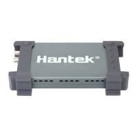
Hantek 6022BE
3. Control Panel
4. The Horizontal Panel
The user can change Time/Div, format in the panel.
5. The Vertical Panel
The user can turn on/off the CH1/CH2. Also the user can change the
CH1/CH2 volt/div, coupling and probe attenuation.
6.
The Trigger Panel
In this panel, the user can change the trigger mode, sweep, source and
slope.
7. It shows the system time.
8. Sample Rate
9. It shows the main time base setting.
10. It shows the CH2 information
Readouts show the coupling of the channels.
Readouts show the vertical scale factors of the channels.
A “B” icon indicates that the channel is bandwidth limited.
11. It shows the CH1 information
Readouts show the coupling of the channels.
Readouts show the vertical scale factors of the channels.
12. Output Window
13.
The markers show the reference points of the displayed waveforms.
If there is no marker, the channel is not displayed.
14. The same as 13.
15. Measure Window.
16
The User’s Manual