11
Before starting
Installation Operation
Screen block
diagram
Function setting Program System setting Specifications
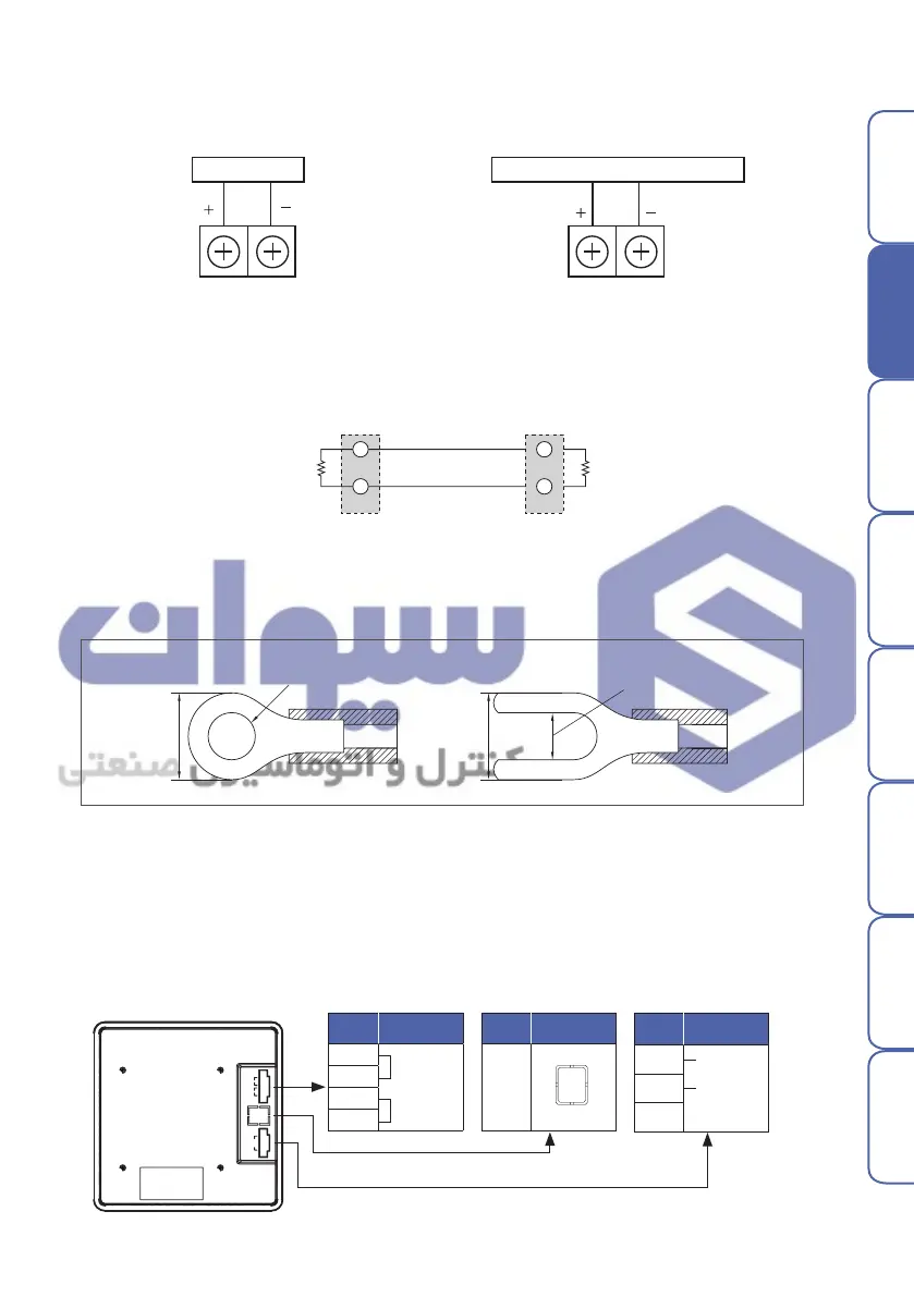
▶ Communication wiring
Connect terminating resistors(100 - 200 Ω, 0.25 W) at both ends of communication cable.
Fig. 3) How to wire for communication
RTX+
Terminating
resistor
resistor
Master
RTX-
RTX+
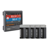
TH510
RTX-
6 ㎜ or
3 ㎜ or more
6 ㎜ or
3 ㎜ or more
▶ Terminal specifications
Fig. 4) Solderless terminal
Power/Input/Output – M3 screw
●
Temperature/Humidity control output
SSR or SCR Recording and indicating instrument, etc..
●
Temperature/Humidity transmission output
●
DC voltage input
●
DC current input
●
Temperature / Humidity control and transmission output wiring
5. Terminal connection diagram
+
1
2
3
4
5
-
DC 5V
6
7
8
COM1
COM2
DO
TM
-
DO
DIDIOMAINPOWER
TM
-
PWR
ADR
PWR
RY2
RY6
RY1
RY5
RY3
RY7
RY4
RY8
COM1RUN COM2
TM
-
DIO
ADR
PWR
RY2
RY6
RY1
RY5
RY3RY4
TH510-MAIN
ADR
TM
-
DI
ADR
PWR
Terminal
No.
Power
1
2
3
4
+
DC 5V
COM1 (제어부)
-
Terminal
No.
RS485
Communication
6
7
8
RTX+
RTX-
Terminal
No.
Ethernet
5
▶ Display
هﺮﮐ ﮓﻧﺎﯿﻧﺎﻫ تﻻﻮﺼﺤﻣ یرﺎﺼﺤﻧا هﺪﻨﯾﺎ ناﻮﯿﺳ ﺖﮐﴍ
 Loading...