Wheel Alignment AXIS500
AXIS500 Manual Instructions
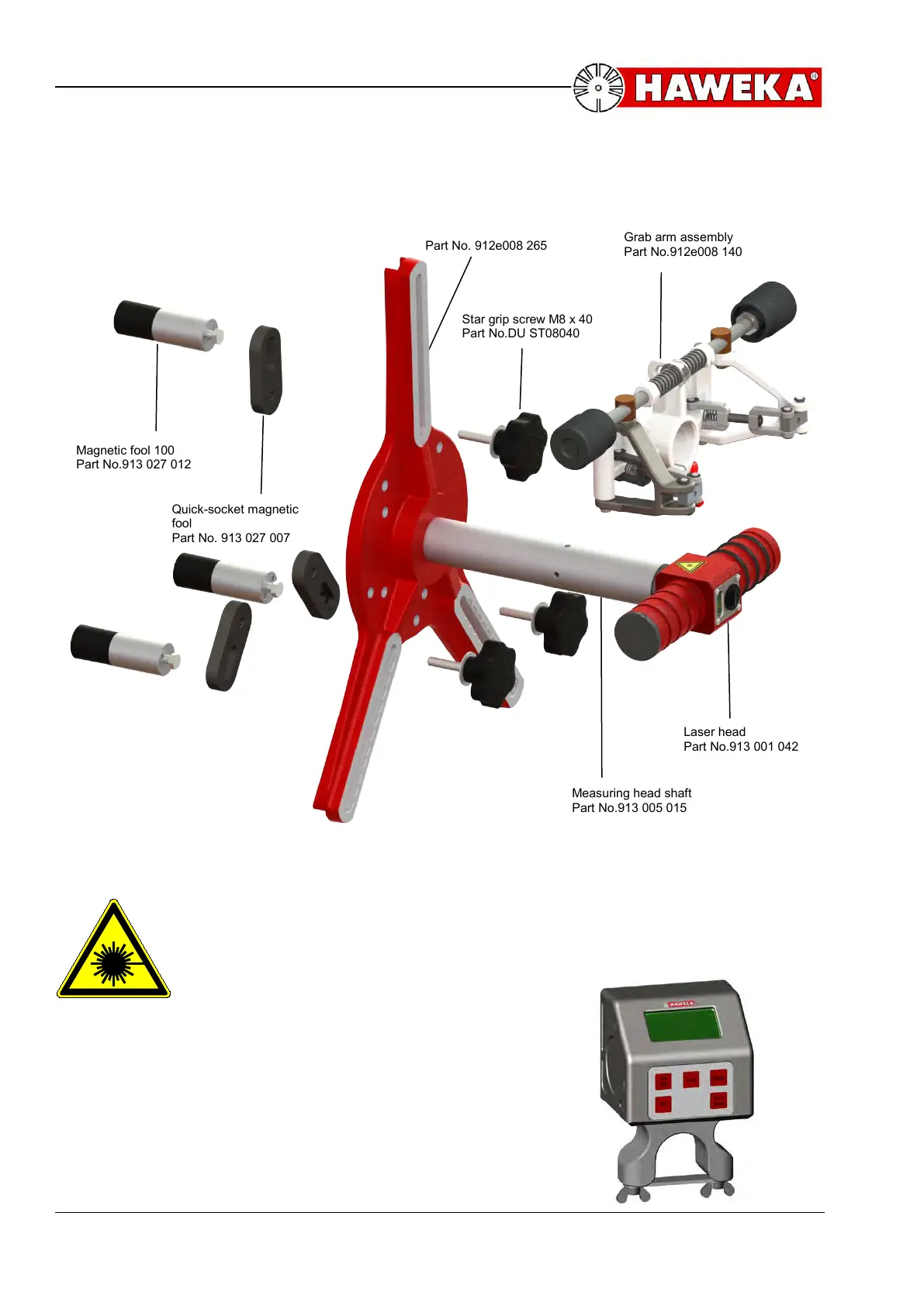
3.2 Design of laser measurement head
Laser head and main components:
Laser head is free rotatable. Ensure that laser beam output opening is
directed downward to the floor after mounting of laser heads and
before switch on of diode laser.
Inclinometer
Required for camber and caster measurement during
front wheel alignment. Electronic inclinometer is
mounted on measuring head shaft.
Part No.912e008 140
Part No. 912e008 265
fool
Part No. 913 027 007
Part No.DU ST08040
Measuring head shaft
Part No.913 005 015
Part No.913 001 042
Part No.913 027 012
 Loading...