Wheel Alignment AXIS500
AXIS500 Manual Instructions
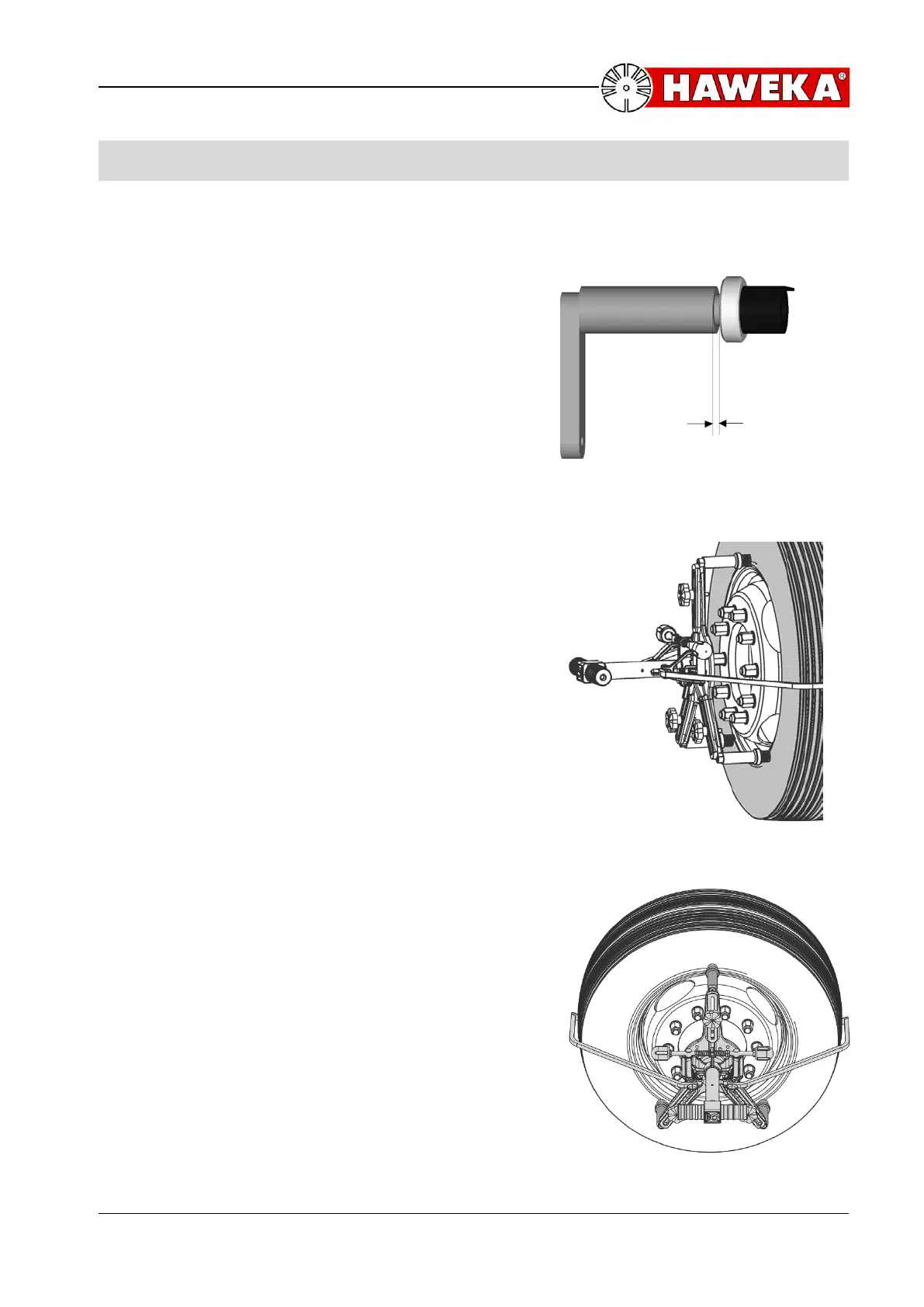
9 Adjustment by Run-out compensation
Preparations
In order to change the magnetic feet for the
runout compensation adaptors it is
recommended to put the measuring head onto
the mounting stand. Loosen the fastening
screws and change the 3 magnetic feet for the
3 compensation adapters. Tighten the adapters
only insofar as you can still move them in the
longitudinal slots of the 3-arm-star. Leave a
play (min. 1 revolution) while fastening knurled
screw of adapter.
Now the grab arms are attached to the grab
arm assembly. The measuring head is centrally
mounted onto the rim by shifting the adaptors
until they correspond to the rim flange
diameter. Illustration 36 shows how the adaptor
feet have to be attached to the rim flange: the
feet are directed towards the wheel hub.
Mounting of complete assembled
measuring head to the rim
With its arms expanded, the measuring head is
first attached to the lower rim flange part. The
single upward arm is not attached yet, but only
moved towards the rim after the lower adaptors
are attached. During this process the adaptor is
shifted so that it presses against the rim flange.
The last locking device is then tightened.
Important: The measuring head is still not
fixed to the rim. The grab arms are now
pressed into the first or second exterior profile
and the quick-clamping device is tightened until
the three adaptors are evenly attached to the
rim. Now the vehicle can be lifted until wheel is
enabled to be turned.
revolution