Wheel Alignment AXIS500
AXIS500 Manual Instructions
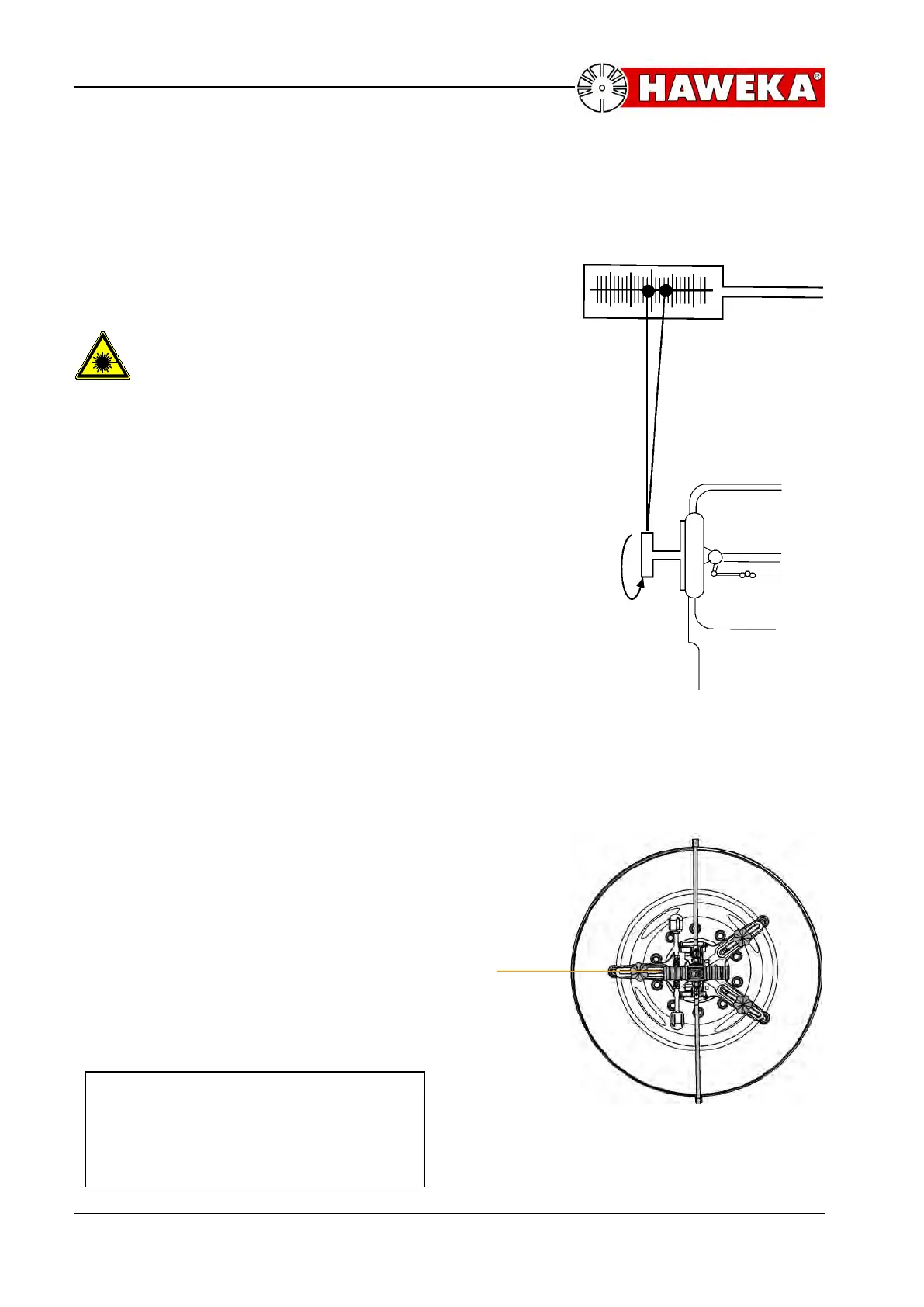
Adjustment by Run-out compensation
Runout adjustment of the laser head:
A toe scale is put in front of the vehicle at a
distance of three meters. Switch the laser on.
Pay attention to laser beam output
opening before switch on!!
The laser point is directed towards the scale
and the latter is set at zero. The rim is turned by
360° while the laser beam points at the scale.
Example: while turning, the point on the scale
travels to the right side of „0“, the fourth scale
line being the maximum value, and to the left
side of „0“, the second scale line being the other
maximum value, resulting in the point’s
travelling over a path of six scale units
A maximum value is set by turning the wheel
again. Memorize from which direction - left or
right - the point approaches the set maximum.
This value is fixed again by shifting the toe
scale to „0“. Afterwards a new value, i.e. half
the distance the point moved during the
revolution, is set on the scale by adjusting the
measuring adaptor. This is done with each
adapter by turning the knurled rings. They have
to be turned to the opposite direction from
which the point approached its maximum. The
three adjusting feet are adjusted up to three
lines. Turn again and check whether the point
still moves on the scale. If this is the case, the
adjustment has to be repeated until the point
no longer moves on the scale when turning the
wheel.
The position is always correctly adjusted, if one
adaptor is located in the same direction on the
layer beam.(Illustration 39)
Final Check:
The laser point must not move
laterally on the toe scale when
turning the wheel.