Wheel Alignment AXIS500
AXIS500 Manual Instructions
Rear Wheel Alignment
6.4 Axle Mismatch in relation to Vehicle’s Longitudinal Axis
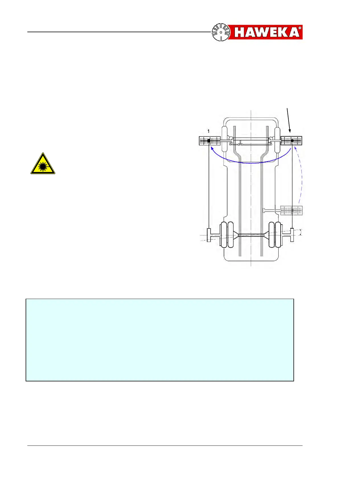
• Attach the magnetic scale to the frame in
the upper range of the front axle.
• Direct the laser point to the scale and adjust
the scale to the halved value indicated for
the axle mismatch. Fix the scale with the
wing nut.
Pay attention to laser beam output
opening before switch on of laser
measuring heads!
• Remove the magnetic scale and attach to
the frame on the opposite side.
• Direct the laser point towards the scale.
This new vale indicated is halved to obtain
the axle inclination value.
• Repeat this measuring procedure with all
other rear axles.
(Illustration 25)
Example, illustration 25,
After completing the axle offset measurement move the magnetic scale to a
position as close to the front axle as possible. Adjust the magnetic scale to the
calculated value of the axle mismatch of 5mm. Next, move the magnetic scale to
the left side as shown on illustration 25 and take the reading with the laser beam.
This reading must be halved. For example purposes, if we have an axle inclination
reading of 3mm that halved value is 1.5mm or the true axle inclination To obtain
the correct value in minutes refer to page 46. If the wheel base D is 6 meters and
the calculated axle inclination is1.5mm then the value in minutes is the intersection
of the diagonal line for 6 meters and 1.5mm.
(see point 6.3)
axle
mismatch