Wheel Alignment AXIS500
AXIS500 Manual Instructions
Front Wheel Alignment
Set-up of Toe Scales (continued)
• The toe scales are shifted on the chalk marking
in front of the front axle until both scales indicate
zero.
Turn the laser housing so that the laser
beam can travel above the floor.
• Fix the length of the toe scale by using the wing
screw and repeat procedure with the second toe
scale – both scales are now of identical length
(illustration 7).
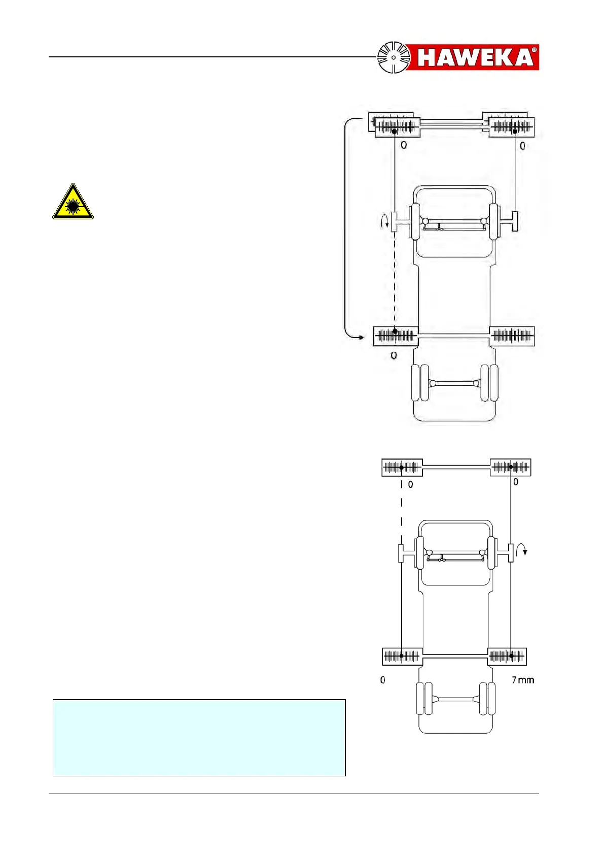
• Now take one scale onto the marking behind the
front axle. – without changing the length.
• Turn the left-hand laser to the rear and shift the
total scale to zero.
Value rear left = 0
Value front left = 0
Value front right = 0
5.4 Toe Measurement and Alignment
Reading of Total Toe:
• Direct the right-hand laser to the rear onto the
toe scale.
• Read the measuring result:
1 long scale line
1,00 mm
1 half scale line
0.50 mm
1 quarter scale line
0.25 mm
The laser point points at zero = The toe is zero
The laser point points inward from zero= toe-out
The laser point points outward from zero= toe-in
• Proceed as follows, if the toe corresponds to the
specified values:
• Note measured value in the test record.
• Check „straight ahead position“ and steering
wheel center position
• look point 5.2 (Alignment of „Straight ahead
position“)
• If the toe does not correspond to the specified
values, toe alignment.
Example:
The laser point on the right-hand side behind the front
axle points at the 7th long outward scale line, i.e. the
front axle has a toe-in of 7 mm.(Illustration 8)